Such an exciting news since Dynaudio and Tang Band do not provide 3inch domes any more.
Also many people including me are dreaming for beryllium dome mid for a long time.
The diaphragm may made by Truextent that we could surmise the price range.
Also many people including me are dreaming for beryllium dome mid for a long time.
The diaphragm may made by Truextent that we could surmise the price range.
Well, good engineering practices dictates that a tweeter need a waveguide which equals the dispersion pattern of the midrange driver. Another rule is that the tweeter and midrange vertical distance is no more than 1 octave, so lets check the math.
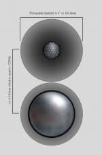
1. The waveguide which in this case has to be at least 3" in diameter, this is equal to 76,2mm. The flange diameter of the midrange is 121m, this is equal to 4.76", which is fine. This mean we can produce a tiny waveguide for the midrange and mount the the driver from behind. So we now have two waveguides 🙂
2. We need to find the maximum length of separation or c/c between the tweeter and midrange, I am gong to use 2500Hz as the XO in this example, but you can recalculate to fit your own need. The next two points of interest is 2000Hz and 3000Hz. This is 1 octave, and we need to find the maximum distance.
The maths.
λ = c / f
where
λ = wavelength (m)
c = speed of sound (m/s)
f = frequency (Hz)
Wavelength of 2000Hz
λ = 331,2m/s / 2000Hz
λ = 0.165m or 165cm
Wavelength of 3000Hz.
λ = 331,2m/s / 3000Hz
λ = 0.110m or 110cm
Difference in length between 2000Hz and 3000Hz.
165cm - 110cm = 55cm .. or 550mm. This is your maximum distance that you would want to have between your tweeter and midrange.
Summery:
The answer to the question of why I am interested in this 3" beryllium midrange driver is to have the ability to match the tweeter with the same material in the midrange. Dissimilar materials, say textile tweeter and aluminum midrange will bring an ever so slightly difference in the tonal and harmonic balance.
The best combinations are between drivers that have similar materials and harmonic content, this together with a properly designed dispersion pattern, aka waveguide coupling between the drivers, are the best option.
We have to remember that our hearing is most sensitive between 1000-7000Hz and so this is where most of the details exist and hence it is the most crucial and demanding area. This area will demand the most of any engineer and the slightest issue here will be noticeable.
Just my 2 cents 🙂
Source: Sound - Frequency, Wavelength and Octave
The answer in my post was that a wavelength of 2kHz is equal to 0.165m (meters) or 16.5cm (centimeter) which is equal to 165mm (millimeters). So a tiny error on my side
The maths.
λ = c / f
where
λ = wavelength (m)
c = speed of sound (m/s)
f = frequency (Hz)
Wavelength of 2000Hz
λ = 331,2m/s / 2000Hz
λ = 0.165m or 16.5cm
Wavelength of 3000Hz.
λ = 331,2m/s / 3000Hz
λ = 0.110m or 11cm
Difference in length between 2000Hz and 3000Hz.
16.5cm - 11cm = 5.5cm .. or 55mm. This is your maximum distance that you would want to have between your tweeter and midrange. One can use the upper distance which in this case is 165mm since this is a full octave distance and you would be safe.
To expand on my initial post which stated that one can use a 4.8mm waveguide, this waveguide is equal to 121.92 millimeters. If you take 2 pcs 4.8" waveguides and place them edge to edge, the c/c becomes 2x the radius of these two waveguides ... or for
simplicity's sake, 121.92mm... This is 26% less than the maximum c/c distance according to the 1 octave rule .. 🙂
Last edited:
Member
Joined 2003
Besides an error of a factor of 10, the logic doesn't make much sense. Based on a crossover of 2500Hz, your determining a 1 octave span and using the difference in wavelength as maximum driver spacing, which comes to 55mm in this case. I don't understand this logic, or the statement of 55mm maximum but 165mm is safe.
You can choose whatever spacing you like, with relation to the polar pattern you may decide that the closer the drivers are the better as it provides the largest "frontal lobe". However following some information provided by the VituixCAD developer, the closest spacing may not provide the best overall power response, where 1.0-1.4x the crossover frequency wavelegth appears to provide the best power response, and 0.5-0.7x provides the worst case result.
Using this simplified logic and 2500Hz example, that would provide an ideal c-c distance of around 165mm (1.2 * 137.6mm)
Reference post: VituixCAD
DcibeL: We do agree, its just a different way of describing things. And I can certainly explain things in a very simple way:
Both rules us using the 1 octave as the base.
😀
Mate your tweeter and midrange with a tweeter waveguide of the same width and depth as your midrange. Place the vertical c/c between them at 1 octave wavelength apart on the vertical plane for best crossover transition and dispersion pattern.
Both rules us using the 1 octave as the base.
😀
Oh, very cool stuff. Thanks for the link.Besides an error of a factor of 10, the logic doesn't make much sense. Based on a crossover of 2500Hz, your determining a 1 octave span and using the difference in wavelength as maximum driver spacing, which comes to 55mm in this case. I don't understand this logic, or the statement of 55mm maximum but 165mm is safe.
You can choose whatever spacing you like, with relation to the polar pattern you may decide that the closer the drivers are the better as it provides the largest "frontal lobe". However following some information provided by the VituixCAD developer, the closest spacing may not provide the best overall power response, where 1.0-1.4x the crossover frequency wavelegth appears to provide the best power response, and 0.5-0.7x provides the worst case result.
Using this simplified logic and 2500Hz example, that would provide an ideal c-c distance of around 165mm (1.2 * 137.6mm)
Reference post: VituixCAD
I am excited about a BlieSMa Be mid. I just wish it was a little smaller. My current 3" eton mid is 16mm smaller.
My guess is $1000-$1200USD ea.. I'm not very good at "price is right" though.
When I was hunting for mids, the Yamaha Ja-0801 (Be mid dome) was something I looked at. That is an old heavy part. It is nice to have a modern option.
My guess is $1000-$1200USD ea.. I'm not very good at "price is right" though.
When I was hunting for mids, the Yamaha Ja-0801 (Be mid dome) was something I looked at. That is an old heavy part. It is nice to have a modern option.
I am excited about a BlieSMa Al mid, because I know I won't be able to afford the Be one. Okay, truth be told, I probably won't be able to afford the Al one either.
I sent Malikov an email with a few questions about the BlieSMa 3" mid dome and this is the conversation.
My questions:
I know these are early days but I can't help myself. I have a few questions for you. regarding the 3" midrange, which I hope you can give some clarity on.
1. Do you have a rough timeline for when we can expect some version of the midrange to be available for measurements?
2. I hope you are planing to release all 3 versions such that they can be mated to their respective tweeter for best material matching ?
3. Do you have an estimate of the cost for these drivers ?
Answers:
[FONT="]
1.[/FONT][FONT="]We are hoping to be able to represent pre-production samples and their measurements in the beginning of June.
[/FONT][FONT="]2.[/FONT][FONT="]We are planning Be, silk and paper versions right about now. Later on maybe AlMg version too.[/FONT][FONT="]
3.[/FONT][FONT="]Unfortunately not yet. Last week we’ve got an information, that neodymium magnets increased their price in 100%. Be domes will be also increased in price, we still waiting for the updated quotation. Currently, the estimated price can’t be calculated. [/FONT]
[FONT="]Mit freundlichen Grüßen / With kind regards,[/FONT]
[FONT="]Stanislav Malikov[/FONT]
Acoustic center.
If someone has the acoustic center or voice coil distance from the diaphragm surface for the Accuton C90-6-724, I would very much appreciate that. I am trying to calculate a waveguide to go with a tweeter for it.
If someone has the acoustic center or voice coil distance from the diaphragm surface for the Accuton C90-6-724, I would very much appreciate that. I am trying to calculate a waveguide to go with a tweeter for it.
Last edited:
1 full wavelength at Fc for the CTC spacing is not very good if you want to avoid nulls in the off axis response.The maths.
λ = c / f
where
λ = wavelength (m)
c = speed of sound (m/s)
f = frequency (Hz)
Wavelength of 2000Hz
λ = 331,2m/s / 2000Hz
λ = 0.165m or 16.5cm
Wavelength of 3000Hz.
λ = 331,2m/s / 3000Hz
λ = 0.110m or 11cm
Difference in length between 2000Hz and 3000Hz.
16.5cm - 11cm = 5.5cm .. or 55mm. This is your maximum distance that you would want to have between your tweeter and midrange. One can use the upper distance which in this case is 165mm since this is a full octave distance and you would be safe.
To expand on my initial post which stated that one can use a 4.8mm waveguide, this waveguide is equal to 121.92 millimeters. If you take 2 pcs 4.8" waveguides and place them edge to edge, the c/c becomes 2x the radius of these two waveguides ... or for
simplicity's sake, 121.92mm... This is 26% less than the maximum c/c distance according to the 1 octave rule .. 🙂
When the sound from the two drivers becomes half a wavelength apart they are completely out of phase and a deep null (total cancellation) occurs.
If the CTC is 1 wavelength at Fc then at just 30degrees off axis you're at half a wavelength (the sine of 30degrees is 0.5), a deep null occurs at Fc. Then as you progress from 30 through 90degrees off axis the null will progressively move down in frequency (and become less severe as the levels of the drivers are no longer equal away from Fc).
If CTC = 1/2 wavelength then the deep null occurs at 90degree off axis which you may or may not care about.
If CTC = 1/4 wavelength then at 90degrees off axis you only get a mild drop of -3dB
1/4 wavelength at 2kHz is 4cm, which is unachievable so there is always going to be a compromise.
How low you need to push the CTC and/or crossover frequency depends on how well behaved the drivers are off-axis by themselves, and how much you're willing to trade-off the (usually vertical) off-axis response for non-linear distortion and power handling. It's much easier to find a tweeter that will happily cross at 1.5kHz rather than 3kHz, than trying to find drivers to reduce your CTC from 10cm to 5cm without compromising performance in some other way...
In most of my designs i'm at about 1/2 wavelength CTC, so the response only gets ugly around Fc for sound directed 90degrees up and down (straight at the roof and floor), which doesn't have a direct reflection path to the listening position anyway in most listening spaces.
Last edited:
^^^^^^^^^^
A response to TMM.
Thanks. I will take this into account as I move forward. When working with the drivers on test baffles, I am sure much of this is evident as one move the drivers around and work on the crossover.
But it sure helps to know that these things have an effect, and it helps in deciding upon which compromise one need to make.
Accuton C90-6-724 mid, and Accuton C25-6-158 (CELL drivers) or BlieSMa T25B-6 tweeter together with Wavecore Balanced woofers should make for a very good combo.
For instance on most ATC speakers, the 104mm tweeter and 150mm mid-dome results in a CTC distance of around 130mm. The Bliesma 67mm T25 and 121mm mid would give a CTC distance of slightly less than 100mm. A difference of around 30% is not to be scoffed at IMHO.
You'd struggle to get the ATC dome close to the tweeter, it has a 200mm magnet!
You'd struggle to get the ATC dome close to the tweeter, it has a 200mm magnet!
I don't know the exact size of ATC mid-dome's magnet, but it is very large indeed. I have just checked using pictures and a "pixel ruler" to measure the relative size of ATC's tweeter and mid-dome with its waveguide, using the known dimensions of one of their speakers (SCM50ASL).
Here is what I got approximately :
Tweeter flange diameter : 87mm (smaller than I thought, maybe the older seas tweeter they used before was larger)
Mid-dome waveguide : 157mm
CTC distance : 128mm
Last edited:
I seriously doubt that the objective performance of these things will exceed the objective performance of any of the Scan-Speak 10/f's, and maybe won't even surpass the Tymphany/Vifa TG9FD's, but if there's a market for ultra expensive 3" domes, then why the hell not🙂
I don't know the exact size of ATC mid-dome's magnet, but it is very large indeed. I have just checked using pictures and a "pixel ruler" to measure the relative size of ATC's tweeter and mid-dome with its waveguide, using the known dimensions of one of their speakers (SCM50ASL).
Here is what I got approximately :
Tweeter flange diameter : 87mm (smaller than I thought, maybe the older seas tweeter they used before was larger)
Mid-dome waveguide : 157mm
CTC distance : 128mm
Then where lies all those wave-guide tweeters with the CTC rule ?
Ignore all the tweeter-wave guide combo not able of a <= 1500 hz cut-off ?
- Home
- Loudspeakers
- Multi-Way
- Some speaker driver measurements...