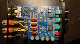
I "accidentally" bought this little amp. Plugged it in and listened a bit, and didn't really fall for it. A little bit of a hiss and slightly "pixelated" sound. Has anyone tried to mod this before? Ideas? 🙂 I was thinking bypassing the volume controls and maybe changing input caps.
Tpa3116D2 Dual Channel Stereo High Power Digital Audio Power Amplifier Board 2X120W Xh M543|Operational Amplifier Chips| - AliExpress
Tpa3116D2 Dual Channel Stereo High Power Digital Audio Power Amplifier Board 2X120W Xh M543|Operational Amplifier Chips| - AliExpress
Member
Joined 2018
Hi vilding-San,
Please take a look...
TPA3116D2 2 channel Amprefire Modification
(Machine Translation)
Google Translate
CyberPit
Please take a look...
TPA3116D2 2 channel Amprefire Modification
(Machine Translation)
Google Translate
CyberPit

i got one of those, lots of hiss gain must be maxed.
I have not played with it yet but soon.
I have not played with it yet but soon.
Hi vilding-San,
Please take a look...
TPA3116D2 2 channel Amprefire Modification
(Machine Translation)
Google Translate
Cool mod! Maybe a little over my commitment level though. I think I'll adress gain and input caps at least. A little unclear about the gain fix from the photos and google translate...
CyberPit
i got one of those, lots of hiss gain must be maxed.
I have not played with it yet but soon.
I´ll keep a look out for that!
Problem with XH-M562, broke down amplifier
Hello,
I use a XH-M562 board. Now I have 3 defect amplifiers. I supply 24 V and load the amp one channel with 4 ohm speaker. 3 amps broke down not playing loud levels, not getting hot. There is a low ohmic resitance between VCC and ground. Does anyone know what goes wrong?
Hello,
I use a XH-M562 board. Now I have 3 defect amplifiers. I supply 24 V and load the amp one channel with 4 ohm speaker. 3 amps broke down not playing loud levels, not getting hot. There is a low ohmic resitance between VCC and ground. Does anyone know what goes wrong?
"a low ohmic resitance between VCC and ground" generally means that the IC is defect. If you have more boards left, try with a 12V supply and an 8 Ohm load. I have not tried that board myself.
I supply 24 V and load the amp one channel with 4 ohm speaker.
Do you have loads on each channel?
Pretty sure that without a load, the amp will self destruct.
Might want to measure and verify the voltage, these amps don’t take much over 24V at all.
Or just use a lower supply as mentioned...
From another posting: The XH-M562 TPA3116D2 board is not really a good choice for a beginner. This is because it is what I will call a "minimum configuration board". You need to add power rail decoupling, eventually an output filter and a heatsink. And, you need to configure the board for correct operation. If you configure the present board for operation without output filter, you can test it with a 9-12Vdc power supply. It is a board you should leave aside until you know more about such class D amplifiers.
Sorry for the not very encouraging message.
It is normally the output filter choke that kills the TPA3116 IC when you operate it without load. In this case there is no such choke. But, when you try it without real power rail decoupling capacitors at 24V supply, you can easily generate voltage spikes above the absolute maximum of 26V and that may kill the TPA3116 IC. It is not a board meant for operation just like that.
Do you have loads on each channel?
Pretty sure that without a load, the amp will self destruct.
Might want to measure and verify the voltage, these amps don’t take much over 24V at all.
Or just use a lower supply as mentioned...
I only use 1 channel, what is the minimum load?
Hey guys,
Tried everything to get the low frequencies running with my 2.0 TPA3116 board but it was not working at all.
So I decided to buy a new one with bass adjusting knob. This one (Nobsound NS-G15 Pro) should go down till 10 Hz according to spec sheet. Tried it out today and get a (barely) hearable sound down till about 20 Hz which is pretty good so far. Buuuut the damping is raising significantly below about 35 Hz. But at least no cut off.
Do you have any quick and dirty idea on how to deal with that issue?
Most of the caps are smd which surprised me a lot. Hope this is not a show stopper for my aim to get low frequency output down to about 20 Hz with the lowest damping as possible even below 35 Hz.
Attached a pic of the board. Please let me know what else I could provide to give you further details.
Attachments
Just checked the input impendance resistors and found a 100kOhm and a 47kOhm resistor for each TPA3116 chip. The inner ends of the two resistors are connected to each other (continuity tested) and the other end of the 100kOhm goes to the TPA chip.
Seems to be a very high gain then and I have the hope that removing the 100kOhm would already bring a great advantage in regards to volume raise for low frequencies (20-35 Hz).
What do you think? Worth a try?
If I do so I loose warranty and the chance of sending back the amp (in Germany we have a 14 days return policy)...
The TI datasheet:
https://www.ti.com/lit/ds/slos708g/slos708g.pdf?ts=1617188781476&ref_url=https%253A%252F%252Fwww.ti.com%252Fproduct%252FTPA3116D2
, Table 1 and Figure 27 show how you can change the amplifier gain and input impedance. 100K/47K most likely implements 36dB gain but an input impedance of only 9K! The reason why you have little low bass may be that the signal coupling capacitors value is to low compared to 9K input impedance. It may also be the coupling capacitor value at the output of the source.
To get better bass, you can lower the amplifier gain and get a higher input impedance. If you remove the 100K resistor, you have a gain of only 20dB (10x) but an input impedance of 60K. You also have less hiss.
Such boards typically need some modification to play best. If you prefer returning the board instead is your decision.
Last edited:
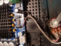
UPDATE: I have removed the 1k resistors and wonder if there is any point in removing these caps?
Anyone? These are the 2 SMD caps near the input.
Hi vilding-San,
Please take a look...
TPA3116D2 2 channel Amprefire Modification
(Machine Translation)
Google Translate
CyberPit
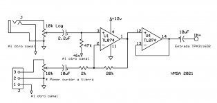
Hi!
Trying to improve a HX-M543 board and looking for information about it, I found the site commented by Cyber Pit very useful. And I reached to the same conclusions. But I made a different modification on the input preamp, which seems practical to me.
Circuit and Photograph testing of the mod implementation. (the legends are in Spanish but I hope you understand) 🙂
Attachments
The TI datasheet:
https://www.ti.com/lit/ds/slos708g/slos708g.pdf?ts=1617188781476&ref_url=https%253A%252F%252Fwww.ti.com%252Fproduct%252FTPA3116D2
, Table 1 and Figure 27 show how you can change the amplifier gain and input impedance. 100K/47K most likely implements 36dB gain but an input impedance of only 9K! The reason why you have little low bass may be that the signal coupling capacitors value is to low compared to 9K input impedance. It may also be the coupling capacitor value at the output of the source.
To get better bass, you can lower the amplifier gain and get a higher input impedance. If you remove the 100K resistor, you have a gain of only 20dB (10x) but an input impedance of 60K. You also have less hiss.
Such boards typically need some modification to play best. If you prefer returning the board instead is your decision.
Thanks FauxFrench - I removed the two 100K resistors. Gain has definitely changed, I need to raise the volume to get the same output. Also the lowest frequencies (20-35 Hz) are not cut off anymore. BUT the volume curve still seems to drop down dramatically below 35 Hz - even with the bass volume being on max. I've now downloaded an win 10 equalizer so that I can adjust the low frequency range manually. It is "okay" now - but still not what I was hoping for.
Pretty bad to have all these smd capacitors on the board instead of some big ones. I am not even able to identify which capacitors are the main input caps and what I had to change to get more bass (20-35 Hz) out of that little amp.
One more info: I am using a 19V 4.7A power supply. Could it have an effect if I changed to a 24V something A power supply? I could try with a lot of effort (I have a 24V power supply on my ceiling for indirect LED lighting - quite a hassle to get it removed from underneath the indirect ceiling...). Worth a try? Could the power supply have an effect on the damping and the dropping of low frequencies? Or is it just "more power in total" then? Power in "total" seems to be fine at the moment.
Increasing the supply voltage should not have a significant influence on the frequency range. My TPA3116 boards are, as far as my rather untrained ears can detect, capable of delivering signals below 35Hz at good volume. I do not think that your missing low bass relates to the TPA3116 part of the circuit. Do you happen to have access to an oscilloscope? On YouTube you can download a frequency scan in the range 1Hz to 100Hz and with that (and an oscilloscope) you can check if your perception of little deep bass is objectively founded.
Apart from a TPA3116 power section, your amplifier board includes a pre-amp section with tone-controls. The reason for little deep bass may relate to this circuit which we unfortunately do not know how is made.
Apart from a TPA3116 power section, your amplifier board includes a pre-amp section with tone-controls. The reason for little deep bass may relate to this circuit which we unfortunately do not know how is made.
Increasing the supply voltage should not have a significant influence on the frequency range.
If my cheapo Scope serves as measuring ground, I did manage to verify it's completely flat if configured right. Either 12 and 24. It might be true that at 12V, you could run into distortion early on. But if you use 20db gain and use something that doesn't have much over, lets say, phone output level, you should barely notice distortion. Yes, you will have less output power in total.
I upgraded one of my boards from 12V to 19.3V (notebook PSU), there was just a slight gain in volume before distortion, nothing I'd call concerning unless you want to use 12V outdoors, not going to too well on open places.
And to everyone who might not know, the TPA3156 apparently are Drop-in replacements for the 3116s that can draw a bit more power as claimed by TI and has lower power consumption when idle. I'm trying to get my hands on some of those to play with 😛
Many thanks for making us aware of the TPA3156. At least I had not noticed it. Seems indeed like a TPA3116 with better output switched (90mOhm compared to 120mOhm), less idle current (for battery use) and a reasonable price (1.60 Eur compared to 1.00 Eur / large amounts). It will probably push out the TPA3116 in the coming years.
Last edited:
Many thanks for making us aware of the TPA3156. At least I had not noticed it. Seems indeed like a TPA3116 with better output switched (90mOhm compared to 120mOhm), less idle current (for battery use) and a reasonable price (1.60 Eur compared to 1.00 Eur / large amounts). It will probably push out the TPA3116 in the coming years.
Be aware that the MODSEL is opposite between the two.
3116 low = BD mode
3156 hi = BD mode
I had a board designed for 3116 (all of mine are) and put a 3156 on it before I found this out.
Had to remove the 3156's and put on 3116's.
- Home
- Amplifiers
- Class D
- TPA3116D2 Amp