Working
Have gotten all functions to work.
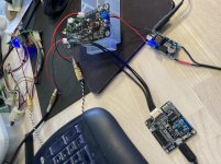
Input, output through ADAU1701 DAC, Output through PCM5102, Analog volume control on PCM5102, general purpose pots, LEDs, Mute control for PCM5102.
Only error, was wrong resistor values, and missing cooling pad for the LDO ... should just have made a pour for it. The LDO fed from 16Vdc gets too hot so have put a small LM2596 between for now.
So now time to make the actual "program" in SigmaStudio.
First version of the DSP is intended as a crossover and control for a party box.
On the picture you can see my new class d amp furthest away ... first tim doing 4 layer PCB ... works like a charm 😀
Have gotten all functions to work.
Input, output through ADAU1701 DAC, Output through PCM5102, Analog volume control on PCM5102, general purpose pots, LEDs, Mute control for PCM5102.
Only error, was wrong resistor values, and missing cooling pad for the LDO ... should just have made a pour for it. The LDO fed from 16Vdc gets too hot so have put a small LM2596 between for now.
So now time to make the actual "program" in SigmaStudio.
First version of the DSP is intended as a crossover and control for a party box.
On the picture you can see my new class d amp furthest away ... first tim doing 4 layer PCB ... works like a charm 😀
Attachments
 Good on ya'!
To the 'How many errors ..' question a post or two back -- pretty sure it is possible to make a bunch more than you have, on a project like this ..
Some really good-looking work there!
Congrats!
Thanks Rick 🙂
On the click less operation of the PCM5102 there still seems work to do.
One thing I realize is that the board uses quite some power, and the capacitor leading in is quite small .... therefore the voltage drops very fast when power is disconnected.
I have a a pin out of the ADAU1701 to control mute of the PCM5102, so need to figure out how best to use this. I think at least at start up you can setup a timer for to delay the un-mute, giving things time to stabilize.
On power down, it's of course all about detecting the power loss. I have nothing really in this circuit to help in this, and had hoped that the PCM was better at detecting this it self.
Well there is always something for a next version.
But really glad that this works as it is a big step forward for my plans to make DSP controlled active speakers (for DIY only). 😉
Mute on start up
Have been playing a bit more with the circuit and the DSP.
All working really well.
As said there is a pop sound when starting up, but not when powering down.
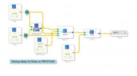
As you may recall I have routed GPIO M3 to the mute pin of the PCM5102.
And by implementing the attached delay in the DSP, the pop at start up is almost eliminated. There is still a very small click, but I guess this is as good as it gets in this implementation.
I'm planning to do a new version with 2 x PCM5102, and with the very few mistakes corrected. Such a version could be used for a 3 way plate amp.
Have been playing a bit more with the circuit and the DSP.
All working really well.
As said there is a pop sound when starting up, but not when powering down.
As you may recall I have routed GPIO M3 to the mute pin of the PCM5102.
And by implementing the attached delay in the DSP, the pop at start up is almost eliminated. There is still a very small click, but I guess this is as good as it gets in this implementation.
I'm planning to do a new version with 2 x PCM5102, and with the very few mistakes corrected. Such a version could be used for a 3 way plate amp.
Attachments
Wonder what an easy, cheap and good upgrade would be for the ADC?
I find PCM5102 very easy to work with ..... anything similar for ADC that someone has actually connected to a ADAU1701?
The PCM5102A achieves a 3 db THD + N improvement getting to -93db
The ADC section is therefore limiting the distortion performance by 10 db now as the ADC for the ADAU1701 is only -83 db.
PCM1861 (HW controlled ... guess this is the right version to use for ADAU1701) only promises -85db, but says typically -93db! ....
Wonder if it is worth the effort?
Member
Joined 2018
FYI: Actual Measurement Data PCM1861/PCM9211/ADAU1701-PCM5102A
Hi Baldin-San,
I have some useful information for you. I have PCM1861(Unbalanced Input) Board, PCM9211 in my TAS6422 Amp and FreeDSP Classic SMD A/B plus II.
So I measured the audio performance for you.
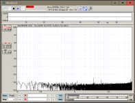
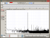
Attached figures are ...
1. PCM1861 ADC Remain Noise (I2S output, fs=44.1kHz)
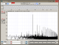
2. PCM1861 ADC FS -1.6dB Distortion (I2S output, fs=44.1kHz)
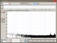
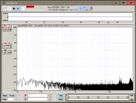
3. PCM9211 ADC Remain Nose (I2S outut, fs=96kHz)
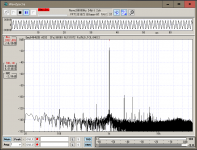
4. PCM9211 ADC FS -1.2dB Distortion (I2S output, fs=96kHz)
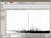
5. PCM9211 ADC FS -7.3dB Distortion (I2S output, fs=96kHz)
6. PCM9211 ADC FS -21.3dB Distortion (I2S output, fs=96kHz)
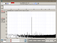
7. ADAU1701 Embedded ADC->DAC Remain Noise (fs=96kHz)
8. ADAU1701 Embedded ADC->DAC Distortion (fs=96kHz)
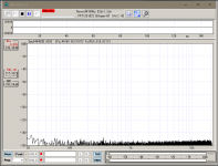
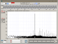
9. ADAU1701 Embedded ADC->PCM5102A DAC Remain Noise (fs=96kHz)
10.ADAU1701 Embedded ADC->PCM5102A DAC Distortion (fs=96kHz)
Perhaps I can say PCM1861 has clean signal performance. PCM9211 large signal performance data indicates some it's characteristics. ADAU1701 embedded ADC/DAC is not so bad compare with it's cost. 🙄
Kind Regards,
CyberPit
Hi Baldin-San,
I have some useful information for you. I have PCM1861(Unbalanced Input) Board, PCM9211 in my TAS6422 Amp and FreeDSP Classic SMD A/B plus II.
So I measured the audio performance for you.
Attached figures are ...
1. PCM1861 ADC Remain Noise (I2S output, fs=44.1kHz)
2. PCM1861 ADC FS -1.6dB Distortion (I2S output, fs=44.1kHz)
3. PCM9211 ADC Remain Nose (I2S outut, fs=96kHz)
4. PCM9211 ADC FS -1.2dB Distortion (I2S output, fs=96kHz)
5. PCM9211 ADC FS -7.3dB Distortion (I2S output, fs=96kHz)
6. PCM9211 ADC FS -21.3dB Distortion (I2S output, fs=96kHz)
7. ADAU1701 Embedded ADC->DAC Remain Noise (fs=96kHz)
8. ADAU1701 Embedded ADC->DAC Distortion (fs=96kHz)
9. ADAU1701 Embedded ADC->PCM5102A DAC Remain Noise (fs=96kHz)
10.ADAU1701 Embedded ADC->PCM5102A DAC Distortion (fs=96kHz)
Perhaps I can say PCM1861 has clean signal performance. PCM9211 large signal performance data indicates some it's characteristics. ADAU1701 embedded ADC/DAC is not so bad compare with it's cost. 🙄
Kind Regards,
CyberPit
Attachments
-
 PCM1861_RemainNoise_to_I2S_44k1.png46.3 KB · Views: 215
 -
 PCM1861_DIstortion_to_I2S_44k1.png47.7 KB · Views: 236
 -
 PCM9211_ReaminNoise_to_I2S_96k.png47.7 KB · Views: 210
 -
 PCM9211_-1dB_Distortion_to_I2S_96k.png52.5 KB · Views: 136
 -
 ADAU1701_to_PCM5102A_DIstortion_96k.png51.1 KB · Views: 173
 -
 ADAU1701_to_PCM5102A_RemainNoise_96k.png47.7 KB · Views: 165
 -
 ADAU1701_to_ADAU1701_DIstortion_96k.png51.1 KB · Views: 154
 -
 ADAU1701_to_ADAU1701_RemainNoise_96k.png48.1 KB · Views: 147
 -
 PCM9211_-20dB_DIstortion_to_I2S_96k.png49.3 KB · Views: 139
 -
 PCM9211_-6dB_DIstortion_to_I2S_96k.png51.5 KB · Views: 152
Thanks a lot CyperPit .... great work 😉
Really helpful information.
Based on this I think I'll just stick to ADAU1701 + PCM5102A for now.
There is actually not that much improvement in performance with the added PCM5102A, but a little, and it solves the pop issue and eliminate the need for extra active filtering, so both a cost and a real estate effective solution.
Thanks for the help.
Will make a new layout with 2 x PCM5102A, and will skip the volume control .... actually seems to work really well just using an internal DSP volume control connected to a simple pot.
Also have found a better type of pot, with "integrated" knob and smaller size
KR Baldin
CyperPit, did you try to use an external clock (with less jitter / higher frequency)?
If so, what could/would you recommend?
Still thinking it would be beneficial to run the DSP at 512xfs to gain twice the amount of instructions per sample. As I read the data sheet this should only be done using an external clock as the internal Xtal circuit is built for 12MHz and not for 24 ....
Also my measurements of the clock shape left some to be desired (but also not sure my measurement setup is totally up for the task ... Rigol 50MHz scope hacked to 100 MHz ... but using 200 MHz probes with spring for GND)
Hope you don't mind breaking in here. Impressed with the work you and others have done. I've learned a lot. My experience with DSP is an old Rane RPM26.
I'm not skilled enough to solder SMTs and chips. Also on a tight budget. I've been looking at Dayton Audio DSPB-K, Ke, ICP1.
Dayton Audio DSPB-K DSP Kernel Board
The 1701 will do what I'd want, but having trouble understanding the limitations. Can I get to the fourth DAC? Can I get stereo digital data into the processor? If so, what would I need to do? Would an external device be needed?
Thanks for helping a rank amateur!
Last edited:
Hi cloudbuster
Thanks 😉
Easiest is to buy the 3 boards the Kernel, the Extension and ICP1. This way you are sure to be up and running from start. The forth DAC is available from the extension port on the Kernel board.
I also started with these boards just to try it out and to get a bit familiar with the DSP and SigmaStudio.
Only hatch in this is the pop sound when turning on or off the device, but this is also true for e.g. MiniDSP
If you are not in for soldering yet, then this is a good option for a start.
I can make the files I use available including the manufactory files, then there is not much to solder, but you need to know a some about electronics to get it all up and running. So maybe for a second try 😉
I'm be working on a version 2 now, hopefully with no mistakes 😉
I can solder, and have experience, just not with SMTs and chips with 3 blonde hair widths between the pins. Back in the day, I was building active crossovers out of Lancaster's book. I can't tell from the documentation what is necessary to get digital into the chip. Happy to know the 4th dac is accessible. Thanks a bundle for your help!
Member
Joined 2018
ADAU1701 is not compatible 512fs
Hi Baldin-San,
I thought same idea at the first time desiring the FreeDSP SMD Classic A/B. But this chip is not compatible with 512fs.
1701 mclk vs max instructions - Q&A - SigmaDSP Processors and SigmaStudio Development Tool - EngineerZone
So If your plan to drive DAC with MCLK in 192kHz, you need to insert T-Flip flop before into the ADAU1701.
My designed boards are easy to change external TCXO. So I will check the jitter-performance difference later...
CyberPit
Hi Baldin-San,
CyperPit, did you try to use an external clock (with less jitter / higher frequency)?
If so, what could/would you recommend?
I thought same idea at the first time desiring the FreeDSP SMD Classic A/B. But this chip is not compatible with 512fs.
1701 mclk vs max instructions - Q&A - SigmaDSP Processors and SigmaStudio Development Tool - EngineerZone
So If your plan to drive DAC with MCLK in 192kHz, you need to insert T-Flip flop before into the ADAU1701.
My designed boards are easy to change external TCXO. So I will check the jitter-performance difference later...
CyberPit
Hi CyperPit-San
Ok, so the maximum core clock cant really be set higher than with an Xtal of 12.288 MHz?
And the maximum is 1024 instructions per sample (48kHz).
I didn't really get that before now. ... makes sense though.
Not really sure that a higher fs will mean lower distortion though,so I'll stick to the 48kHz and get the maximum # of instructions.
For correcting speakers 1024 is already a pretty low number if you e.g. ae using a FIR filter .... but probably good enough though 🙂
As for jitter: a relative low cost clock like SIT8920 has a jitter of 1.3 pS .... not bad 😉
Question is whether the internal PLL clock is much worse ... no real reason why it should be
Clock jitter in ADAU1701 - Q&A - SigmaDSP Processors and SigmaStudio Development Tool - EngineerZone
Member
Joined 2018
Hi Baldin-San,
DSP core frequency will be the same, even if the 512fs MCLK is possible. You can execute 1024 instructions@48kHz, 512 instructions@96kHz, 256 instructions@192kHz
I wonder actual jitter-performance will be depended on a DSP embedded PLL performance as well... (I'm not sure this)😕
Actually, yes with X'tal. It seems possible to use 24.576MHz (up to 27.8MHz?)TCXO with different PLL setting. (Mode0=1, Mode1=1, Not tested yet)Ok, so the maximum core clock cant really be set higher than with an Xtal of 12.288 MHz?
DSP core frequency will be the same, even if the 512fs MCLK is possible. You can execute 1024 instructions@48kHz, 512 instructions@96kHz, 256 instructions@192kHz
I wonder actual jitter-performance will be depended on a DSP embedded PLL performance as well... (I'm not sure this)😕
Hi CyperPit-San
Yes I think you are right that when using a Xtal, the jitter performance is much determined by the PLL in the DSP.
If you use an external clock, I guess it will still go through the internal PLL ... not sure how this will have impact on performance.
And maybe also back to my question from some time back; how does the external components for the PLL circuit impact performance.
I use X7R for the 2 capacitors in the PLL low pass filter ... X7R is somewhat prone to microphonics ... I guess this could mean jitter.
So should maybe again consider using NP0 or film for these?
56nF NP0 can be had in 1206, should be ok.
Version 2 almost ready for production
Working on Version 2, and close to sending for "production"
New:
- 2 x PCM5202A (not using the outputs from the ADAU1701)
- Analog volume control removed and one more "digital" pot added
- Pots changed to 9mm ones with "integrated knob" (shaft with indicator)
- 3 LEDs with proper drivers
- PLL low pass filter with room for NP0 caps
- Cooling area on top layer for LDO
- 4 layer PCB, with separate layer for 3V3 and GND (it's only 6 USD in total) as it seemed a bit impossible to do the 2 PCM5102A without destroying the GND layer
- 10uF electrolytics changed for 0805 Y5R 10uF ceramics to save a bit of space and as it is much cheaper and probably more reliable
- Divider added on each output, to make it possible to run the DAC to full 2Vrms while connecting to power amp with sensivity of e.g 0.7Vrms
Output terminals changed from JST to small terminal blocks, but kept the u.fl coax to easily connect to power amps with this same connection
Hope I go it all correct 😉
Attachments
Member
Joined 2018
Experimant on ADAU1701 Master Clocks and PLL Loop-Filters
Hi Baldin-San,

But I could find out using with SDR HackRF-One with 0.1ppm TCXO to see the Clock-Jitters. I also tested with my Modified Emu-0404USB to see the audio-able Jitter-Affects.
Result1: HC49U Crystal vs ASFLMB-12.288MHZ-LR-T
(Comparing OSCO clock output via 74LV541A)


MEMS-TCXO has some wide spread-ed skirt shape than Crystal. This means Crystal has lower Jitter performance.
Result2: Modified Board using with External Clocks
This test compares 256fs(AUDU1701 pin38=L) and 512fs(AUDU1701 pin38=H) for ASVMB-24.576MHZ-LY-T.


To see the actual audio affect, I measured the BCLK clock jitters. But I could not see the remarkable differences. Also in the audio-able J-test result.
Result3: PLL Loop Filter Modification
I think the temperature-capacitance curve is not a big matter for audio jitter performances. The phase noise of PLL is the most important factor for Audio-able affects. The lower PLL-Loop-Filter cutoff frequency provides stable locked-clock output, in other hands Lock-up time will be increased anyway.
So I tested three cases, without 3n3 Cap, Normal as original and Added 100nF.


You can see the waterfall part difference. Lower cut-off frequency produces sharp and stable I2S clocks.
I Also tested Audio-able difference compare with ADI suggested and 100nF added case.


12kHz Spectrum skirt shape is different, those differences are extremely small but there is a difference !
I hope this information will be useful for you and all the diyAudio members.
CyberPit
Hi Baldin-San,
Sorry, takes much time. I did some experiment on my FreeDSP Classic SMD A/B. Those are as follows.As for jitter: a relative low cost clock like SIT8920 has a jitter of 1.3 pS .... not bad 😉
Question is whether the internal PLL clock is much worse ... no real reason why it should be
Clock jitter in ADAU1701 - Q&A - SigmaDSP Processors and SigmaStudio Development Tool - EngineerZone
- Experiment-1: Crystal vs MEMS-TCXO
- Experiment-2: External Clock of 256fs/512fs
- Experiment-3: PLL Loop Filter Cut-Off Frequency Change
But I could find out using with SDR HackRF-One with 0.1ppm TCXO to see the Clock-Jitters. I also tested with my Modified Emu-0404USB to see the audio-able Jitter-Affects.
Result1: HC49U Crystal vs ASFLMB-12.288MHZ-LR-T
(Comparing OSCO clock output via 74LV541A)
MEMS-TCXO has some wide spread-ed skirt shape than Crystal. This means Crystal has lower Jitter performance.
Result2: Modified Board using with External Clocks
This test compares 256fs(AUDU1701 pin38=L) and 512fs(AUDU1701 pin38=H) for ASVMB-24.576MHZ-LY-T.
To see the actual audio affect, I measured the BCLK clock jitters. But I could not see the remarkable differences. Also in the audio-able J-test result.
Result3: PLL Loop Filter Modification
I think the temperature-capacitance curve is not a big matter for audio jitter performances. The phase noise of PLL is the most important factor for Audio-able affects. The lower PLL-Loop-Filter cutoff frequency provides stable locked-clock output, in other hands Lock-up time will be increased anyway.
So I tested three cases, without 3n3 Cap, Normal as original and Added 100nF.
You can see the waterfall part difference. Lower cut-off frequency produces sharp and stable I2S clocks.
I Also tested Audio-able difference compare with ADI suggested and 100nF added case.
12kHz Spectrum skirt shape is different, those differences are extremely small but there is a difference !
I hope this information will be useful for you and all the diyAudio members.
CyberPit
Hey CyperPit-San
Wooou ... super work
I'm sorry I'm making you do all these test but for sure I think it should be very interesting results to anyone working with DSPs and DACs.
Looking at all the results, and if I read them right, best result is the standard way, with a crystal directly on ADAU1701 and with the normal filter values.
The last 2 pictures of the distortion + noise, there also it seems that that normal filter walues are the best .... noise raises quite some with the 100nF.
Thanks a lot for all your work 😉
May be a good input to all that are spending money on expensive audio clocks, with no means or no want to measure the difference .... if any 😉
One question: you mention using a 74LV541A in the first example ... is this just for buffering and better measurements?
As I mentioned in a previous post, I don´t get a very sharp square on OSCO on a scope ....
In version 2 I'll have 2 x PCM5102A and both connected to OSCO with each a 100 ohm resistor.
Was wondering if a high speed buffer would be better .... on the other hand a PCM5102A only draws 10uA at the logic input (at 3.3V that is 330k ohm impedance), so with 2 DACs is a load on OSCO of 165k ohm.
Thanks and kind regards Baldin 🙂
Last edited:
For some added info layout and components when using the PCM5102a, then this vid may be of help, the presenter is the designer of the PCM5102a:
PCM5102 Audio DAC - A quick look at Aliexpress' best! - YouTube
PCM5102 Audio DAC - A quick look at Aliexpress' best! - YouTube
- Home
- Source & Line
- Digital Line Level
- ADAU1701 based DSP for sub or 2 way