Hey there, glad to read that Per did it again 😀
I have to be patient because of the design of the RB-991's and its high voltage running the pcb's, designing the last upgrade (current mirrors) is giving Per headaches but on the other hand every time i did an upgrade that Per told me to the amps took a real step to better level.
Therefor i'll wait patiently 🙂
Hi,
There is nothing on a RA-931 pcb (working or faulty) that ever gets so hot that it should cause any off-gassing or smells. And I have had my nose down on quite a few 931's over the years!
The only bad 'smell' I have met comes if the amp has been sitting in a heavy smoker environment. The nicotine seems to cling to the inside dust and surfaces, and the entire amp and pcb requires a major clean and washout.
Switches and pots will also need a good dose of contact cleaner, but do that separately.
Best,
Per
Hi,
Recently acquired Rotel RA-921 at ebay in fully working condition just with fuse blown. Visual examination and measure of components not indicated any fault. So fuse was replaced, amplifier turned on, and that's it - amplifier fully working. But…
I was not impressed of the sound at all. Tried to audition only power amp by omitting op-amp and remove el.capacitors in sound path. Still not impressed. Gave up and decided to use that amplifier as a donor for case, psu and heatsink, so removed (de-soldered) all components from power amplifier section.
But after few days out of nothing to do, changed my mind and soldered everything back as I have got another - better donor for case - different brand of faulty amplifier, and as Rotel was not really faulted, thought to give him another chance.
Anyway, interesting exercise.
Only in between de-soldering and soldering back, I have checked all components for failure, paired all transistors by hfe, cleaned PCB both sides especially back side from soldering flux remains that came PCB from factory - unwashed - sticky. Put all back. Power transistors got fresh thermal compound.
Cleaned volume pot with contact cleaner/lubricant as it was some sign of "whispering" at 10h-11h position while adjusting volume. After cleansing it gone.
Now interesting part - result.
Magic happened! Sound became so good, so attractive and involving, that I can't stop listening, impossible to make a break. So huge improvement - could not imagine that it would be possible with the same "initially not impressive" amplifier without modding circuit by a bit.
DC offset before those refurbishment measures was 300mV, now 30mV on both channels.
Sound is clear wide - with strong bass - full bodied, but not sharp and hi freq as common transistor amps deliver. Just pleasant - comfort sound. And I like how it performs low freqs. Just beautiful!
So advice: before hard modding, please do perform those "must have" measures for aged equipment. You will be surprised by the result! And do not underestimate cleaning of flux and dirt/dust.
Best,
Kes
p.s. as for upcoming mods I would see to separate power amp input section from output stage in power supply +-rails by introducing small value resistor (20-100ohm) with good quality el.cap. (220-470uF). That tiny change was mandatory in every amplifier design from valve amplifiers age, but somehow Stan Curtis have his own view on "must-have/mandatory" measures.
Hi Kes,
Interesting story. If you had 300mV offset - then the blown fuse was clearly not the only problem with the amp.
Your de- and re-soldering has probably repaired or shocked the faulty component(s), but with a blown 4AT speaker fuse I would still suspect that (some of) the power transistors may have had a pretty rough time, and I would replace all four with modern linear ON or Sankens.
Input stage rail filters are great, although a bit fiddly to put in with pcb track cutting and drilling, etc.
Also, I find that if you manage to precisely match the hFE's of the LTP and their DC loads, offset will drop below 3mV and the PSRR spike up to a level that renders these filters unnecessary.
Just my 2p.
Best,
Per
Hi Per,
thanks for response. Regarding changing outputs I am considering that option.
Just need more info...
I have replaced once one faulty channel in Yamaha AX-400 with ON:
FJA4310OTU/FJA4210OTU. Charts in datasheets looks identical to original transistors used by Yamaha. And for comparison left other channel originals.
And by comparison of R / L channel speakers I found that ON produces better sound but just by a bit differently from Yamaha originally used 2SC3182/2SA1265. And all difference was only slightly not as sharp as originals sounding at hi freq. ON sounded by a tiny bit "naturally softer" at very top, which in Yamaha circuit was benefit. Then I fitted the other channel with the same ONs to finish repair.
Wonder if you had experience with those ON transistors, or different ones, designed for audio: NJW0281G/NJW0302G how those sounds?
I'm looking for transistors which would be "natural" sounding without too much brightness/sharpness at the very top freq. range. But not too much "soft-rounded".
Kind regards
Kes
Hi Kes,
I have mostly used NJW0302/0281 (and their big brothers 1302/3281) and Sanken C3263/A1294 - and I must admit that I find it very difficult to hear any real difference in 'sound' - they all definitely work absolutely fine.
Some say that they are 'better' than the original (now discontinued) Sanyo 2SD1047/2SB817 mainly because their hFE remains more linear over the full range of collector currents.
Well, since my days in a rock band I rarely play music that requires >4A / 130W output into the woofers - and if I did, my ears would probably start distorting more than the amp (and speakers).
Regarding the L/R old/new comparison, remember that transistors - and in particular power trannies do drop in hFE over time (the old Sanyo's sometimes by up to 50%) which in turn gives a greater load back onto the drivers and the VAS, possibly leading to some non-linearity and thus a change in 'sound'. Whether it gets 'softer' or 'sharper' depends on whether this loading primarily produces even or odd harmonics, IMHO.
So, whenever there is a power transistor issue, I always swap all of them.
Best,
Per
Just wanted to share couple of thoughts about my Rotel RA-921 modding.
So I was initially not impressed with the sound of stock Rotel I have bought from ebay as "faulty" but fault was only blown L-ch speaker protection fuse.
After de-soldering-cleaning-pairing and soldering back, some "life" in sound was observed. So thought it can be keeper for future moddings.
I must admit that I found stock Rotel sound interesting, different from "common" commercial transistor amplifiers. But of cause there was some issues with lack of cleariness in mid-high frequency. Despite "not-so-clear" sound had some "musicality" and "full-bodiness", kind of interesting-attractive-involving.
So yesterday I invested couple hours in this amp. Installed some Elnas for Audio, Silmic II, some Panas FR, FM, FC. And for the same gave a try to change VAS compensation from "shunt" to "Miller", by removing R623,C607 and added Milled Cap into ready to use empty holes next to Q611.
After turning on and first audition followed huge disappointment what I heard. The "Rotel-ish" sound was completely gone, and the "new sound" was way to bright and to harsh for my liking. This was exact type of sound I was trying to avoid in my systems.
Long story short - today have put all back as it was in original circuit, with one exception - "shunt" capacitor C607 replaced with smaller 220p to lift-up frequency range for correction, with hope that filtering will not overlap with audible range in hi freq as it was with 330p.
And now I can tell I'm happy with the sound! The same "Rotel-ish" sound came back, and as far I can tell, it has less "rounded" or "mudded" sound in hi freq.
So my idea is - if you like "stock Rotel type" of sound in general, but not happy with lack of cleariness in hi freq, please give a try to play with values for "shunt" capacitor at first. It is super essay mod, just one part to replace per channel.
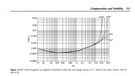
I believe that in this place 330p is far to big value. Self Douglas in his book measured distortion figures having range of applicable values 10p-37p. With values bigger than 280p amplifier THD showed very poor results starting with 20kHz. see page 350 diagram 13.27.
Might be that Stan Curtis prototyped this amp circuit with 33p, but then some sort of typo happened to 330p.
Worth to try smaller values for C607 to find smallest which ensures stabile work and for the same will not cut hi frequencies.
As for VAS Rload resistor R623 (33k) it might be also area to play...
If to apply valve amp logic, driver's anode Rload value for best sound is 3-5x R-internal of driver valve. As driver valve sounded never best with close to infinity R-load. Not sure if that applicable there...
Kes
p.s. now while writing enjoying sound of "new more open but stock Rotel" amp thorough headphones. Impossible to stop listen. The only one chance to stop it - if you will click "Pause" while in between tracks... If you missed that couple of seconds of silence, and new track started, you will be chained/nailed to your amp till the next tracks change...
So I was initially not impressed with the sound of stock Rotel I have bought from ebay as "faulty" but fault was only blown L-ch speaker protection fuse.
After de-soldering-cleaning-pairing and soldering back, some "life" in sound was observed. So thought it can be keeper for future moddings.
I must admit that I found stock Rotel sound interesting, different from "common" commercial transistor amplifiers. But of cause there was some issues with lack of cleariness in mid-high frequency. Despite "not-so-clear" sound had some "musicality" and "full-bodiness", kind of interesting-attractive-involving.
So yesterday I invested couple hours in this amp. Installed some Elnas for Audio, Silmic II, some Panas FR, FM, FC. And for the same gave a try to change VAS compensation from "shunt" to "Miller", by removing R623,C607 and added Milled Cap into ready to use empty holes next to Q611.
After turning on and first audition followed huge disappointment what I heard. The "Rotel-ish" sound was completely gone, and the "new sound" was way to bright and to harsh for my liking. This was exact type of sound I was trying to avoid in my systems.
Long story short - today have put all back as it was in original circuit, with one exception - "shunt" capacitor C607 replaced with smaller 220p to lift-up frequency range for correction, with hope that filtering will not overlap with audible range in hi freq as it was with 330p.
And now I can tell I'm happy with the sound! The same "Rotel-ish" sound came back, and as far I can tell, it has less "rounded" or "mudded" sound in hi freq.
So my idea is - if you like "stock Rotel type" of sound in general, but not happy with lack of cleariness in hi freq, please give a try to play with values for "shunt" capacitor at first. It is super essay mod, just one part to replace per channel.
I believe that in this place 330p is far to big value. Self Douglas in his book measured distortion figures having range of applicable values 10p-37p. With values bigger than 280p amplifier THD showed very poor results starting with 20kHz. see page 350 diagram 13.27.
Might be that Stan Curtis prototyped this amp circuit with 33p, but then some sort of typo happened to 330p.
Worth to try smaller values for C607 to find smallest which ensures stabile work and for the same will not cut hi frequencies.
As for VAS Rload resistor R623 (33k) it might be also area to play...
If to apply valve amp logic, driver's anode Rload value for best sound is 3-5x R-internal of driver valve. As driver valve sounded never best with close to infinity R-load. Not sure if that applicable there...
Kes
p.s. now while writing enjoying sound of "new more open but stock Rotel" amp thorough headphones. Impossible to stop listen. The only one chance to stop it - if you will click "Pause" while in between tracks... If you missed that couple of seconds of silence, and new track started, you will be chained/nailed to your amp till the next tracks change...
Attachments
Last edited:
Downloaded all available service manuals for Rotel Integrated amplifiers, and seems that all of them starting from '80s have exactly the same VAS topology: single transistor with shunt type correction loaded to the ground as 33k resistor paralleled with 330p capacitor.
So we can say that those 2 VAS components: "33k||330p" is the "thing" which shapes special "Rotel" sound.
Now in terms of "lack of clarity" in RA-921, there are couple more places where to check for improvement...
1st - power amp input grounded with cap 750p, which in later models was changed to 220p and recent ones all have 100p.
2nd - need replace all ceramic caps with film type caps as I remember opinion from some audiophile forum that all ceramic caps from audio path must be replaced as ceramic caps "killing the sound".
Kes,
I know this thread has become very long, so I try to restrict further posts to new insights or issues - and not repeat myself. And I would ask other posters on this thread to do the same, please.
Yes, that was what I said (and PM'ed you to read) in post #554 - but OK, here it is again:
The Rotels were designed by Stan Curtis in the UK and he maintained the heavy dominant pole shunt compensation throughout almost all Rotel designs. Quoting Self - who in turn quotes Peter Baxandall: "The technique is in all respects sub-optimal", which for Peter was strong language indeed".
But it gave the Rotels their distinctive, easy listening soft, rounded and 'pleasing' sound. And you can't argue with the impressive sales figures that this did indeed appeal to a lot of people.
Removing the 330pF||33k VAS load and replacing with a better VAS Miller 'collector to base' feedback capacitor design suddenly removes the 'pleasantry' veil and make all the stars come out in detail. Do the Miller compensation right and you can also readily get rid of the 150pF PNP driver load without any stability concerns.
I don't recall ever having seen 750pF as an input RF block capacitor in any Rotel, I think that it is a misprint of 150pF in the old schematic. (And also 750p is not a standard value which would have made it unnecessarily expensive for what it is).
Your 921 has a RF filter of 1k8 and 100pF, which has a -3dB point of 884kHz. If you can hear or make clarity improvements in that frequency range, I take my hat off for you.
Secondly, there are no ceramic caps in the audio path. You should take the claims on the 'audiophile' forums with a pinch (or rather a shedload) of salt - unless they are supported by solid measurement evidence.
Otherwise, at best - your bank account balance will sit on top of a deep placebo effect sinkhole.
Per
I know this thread has become very long, so I try to restrict further posts to new insights or issues - and not repeat myself. And I would ask other posters on this thread to do the same, please.
So we can say that those 2 VAS components: "33k||330p" is the "thing" which shapes special "Rotel" sound.
Yes, that was what I said (and PM'ed you to read) in post #554 - but OK, here it is again:
The Rotels were designed by Stan Curtis in the UK and he maintained the heavy dominant pole shunt compensation throughout almost all Rotel designs. Quoting Self - who in turn quotes Peter Baxandall: "The technique is in all respects sub-optimal", which for Peter was strong language indeed".
But it gave the Rotels their distinctive, easy listening soft, rounded and 'pleasing' sound. And you can't argue with the impressive sales figures that this did indeed appeal to a lot of people.
Removing the 330pF||33k VAS load and replacing with a better VAS Miller 'collector to base' feedback capacitor design suddenly removes the 'pleasantry' veil and make all the stars come out in detail. Do the Miller compensation right and you can also readily get rid of the 150pF PNP driver load without any stability concerns.
Now in terms of "lack of clarity" in RA-921, there are couple more places where to check for improvement...
1st - power amp input grounded with cap 750p, which in later models was changed to 220p and recent ones all have 100p.
2nd - need replace all ceramic caps with film type caps as I remember opinion from some audiophile forum that all ceramic caps from audio path must be replaced as ceramic caps "killing the sound".
I don't recall ever having seen 750pF as an input RF block capacitor in any Rotel, I think that it is a misprint of 150pF in the old schematic. (And also 750p is not a standard value which would have made it unnecessarily expensive for what it is).
Your 921 has a RF filter of 1k8 and 100pF, which has a -3dB point of 884kHz. If you can hear or make clarity improvements in that frequency range, I take my hat off for you.
Secondly, there are no ceramic caps in the audio path. You should take the claims on the 'audiophile' forums with a pinch (or rather a shedload) of salt - unless they are supported by solid measurement evidence.
Otherwise, at best - your bank account balance will sit on top of a deep placebo effect sinkhole.
Per
After thrown away input filtering caps C603/604 (in RA-921 750pF) I can tell I hear biggest influence in getting back sound openness.
Double checked by A/B with turned on amp with headphones, and putting back those caps into holes from soldering side of PCB. Definitely those caps cutting hi-frequency.
Done a little bit of math.
If to count resistance in series which sees LTP input, it gets to following:
1k8, 10k (half of tone reg for treble (if treble setting is on 12:00)), 1k5. In total 13k3.
So freq cut point is 15955Hz. No wonder it kills clarity and details!
Now if to take all value of treble pot 20k, in total resistance will be 23k3. And freq cut will be @ 9100Hz. That worries even more... What engineers have been thinking?
So for RA-921 biggest cap should be 300p.
For those amps where volume pot is just before LTP input, e.g. RA-840b 50k, lowest value must be 100p. So RA-840b, RA-921 etc owners have to replace 300p with 100p. It is a must!
So for my case to fine tune amp to acceptable sound quality, while keeping stock Rotel circuit topology, only few changes required:
1. VAS shunt cap replaced to 220p
2. Input filtering cap replace to 100p or throw it away. Transistor capacitance will do required feq cut-off.
3. Recapping all to Elna/Panasonic FC FM.
4. Clean / replace volume pot.
Now my Rotel no longer requires tweaking. Not bad to get grown-up sound from amplifier for £20 from ebay!?
And move on to next project - restoring CA A300...
Oops, I stand corrected. You were right.
In honesty, I haven't spent much time on the extreme budget RA-920 series and plainly forgot that they don't give the option of bypassing the tone controls. No way to get phase linearity through those.
However, your calculations are missing the fact that the bass section is in parallel with the treble control, so things are not as bad as you point out.
And the treble cut would be in the bottom (not top) setting, where the circuit is supposed to cut the high frequencies as it is.
Have you ever measured the actual frequency range of the amp?
In the RA-931, I tried to apply a 100kHz square wave to the input and scoped the response on the output. I found that the 100pF gave a slight overshoot on the rising edge, increasing it to 150pF solved that. But was it worth replacing the caps for that? I decided that 100kHz was overshooting my hearing aid range.
Now to be constructive, if your amp still has the old TL072 in the preamp section, you could try replacing it with an OPA2134 or a LM4562.
Otherwise, if you love the amp and decide to leave it as it is now, just enjoy the music!
Per
Hi.
I have a Rotel RA-930BX here I'm giving a service. As this is the ultimate Rotel thread I thought I'd jump in and see if there are any little improvements I can try. The recent posts about changing cap values have me interested.
I've had it in storage for years, the output fuses were blown. Dreaded glue was hardened in the regulator section, zeners corroded. Lots of cold solder joints in the power amp sections.
After reflowing the joints (with my favourite solder from '83), replacing fuses and removing the glue it sounds really good. The bias is stable and all voltages are good.
It has the TL052CP Opamp in the preamp tone control section. It's a chip I'm not aware of. Is it as noisy as the TL072? The phono stage has a NE5532AN, I'm ok with leaving that.
I also replaced the 4A bridge rectifier with an 8A one. I have lots of new Panasonic, Rubycon and Nichicon 10,000uF 50v caps I may try, originals are 8,200uF 50v. I have the replacement diodes and multiturn pots on the way.
Last edited:
Hi,
I vaguely remember that the TL052 was the low offset, the TL062 the low power (but slower) versions of the TL072. None of these are particularly low noise or low distortion - as measured by today's standards.
But hey, they were designed back in the mid-70'ies and got extremely popular - in part due to their low bias JFET input, ease of use and affordability.
As I suggested to Kes, you could try replacing it with OPA2134 or LM4562, note that you should limit the regulated supplies to less than +/-18Vdc so you may have to redo the zeners again.
Then you can consider the upgrades which I described in posts #527 - 554, you ears will thank you for it!
BTW, why do you want to replace the diodes?
Per
Hi AngelP,
Thanks for your suggestions. I'll check out those posts.
I was thinking of doing some mods to install the LM317/LM337. I'm guessing they would be less noisy than Zener regulation. I'd be interested in your thoughts on that, does the regulation noise in general make much difference? I understand there's better regulation than linear regulators yet not sure how beneficial can be.
I'm replacing the Zeners as they were covered in glue. They still work yet legs were slightly corroded. Just precaution really.
Much appreciation to all your guidance to myself and everyone along the way
Hi,
I have measured the stock zener regulator ripple to be below 1mVac, which is absolutely acceptable. Further, the opamps have a PSRR of somewhere below 100dB, so they will easily cancel that out.
I'm all for improvements, but that seems to me as an unnecessary effort (and quite fiddly to do).
I have read claims about some Rotel glues being corrosive, but must admit that I have never found it to be so in all the upgrades I have done.
(Quite contrary to the early SONY amps, where the goopy glue they used back then became seriously corrosive when exposed to humidity and munched away the copper pcb tracks. There was actually a Service Bulletin alert sent out on that.)
Anyway, I always meticulously scrape away old glue to get a level fit to the pcb when installing new reservoir capacitors, and using non-corrosive Dowsil 3140 as vibration restraint.
Per
Thanks Per, I trust your judgement. I'm thinking of having a play with the Opamps mentioned and adjusting the Zeners to suit. I have those Opamps available and sockets.
I have about 50 amps in the storage unit that I'm slowly restoring, if needed, it's not the most ideal humidity. I've noticed on some CA and NAD gear from the 90s has bad corrosion so far. This wasn't as bad tbf. Interesting about Sony's, I have some Sony gear there.
I'll check out the Dowsil 3140, not heard of that before and seems you have a good process there.
This amp has the Black Gates caps. I wanted to see what the fuss is about them. I had replaced them with Nichicon Muse and Fine Gold's I had spare. I couldn't tell much difference. I tried them in another amp though, which had new caps, and made a nice change to the lower frequencies upto about 1kHz. More dynamic. I have a Parasound Pass Labs DAC with lots of Black Gate caps that I was thinking of replacing for new but I think I'll leave that now. I like that DAC alot, as with my other modern DAC's.
I'll take a drive to Peak this week to get a new Atlas ESR metre, it's not far from me. Do you recommend any of their other equipment they sell?
Hi Per
1. And most important: Very interesting thread!
2. Some time ago you published a composite VAS including a third T3. In your example, T3 acts at the same time as the buffer for T2 and also as a "current splitter" by T3's VBE paralleled by the 330 ohm resistor. In your example, this might set the IC for T2 as some 0.7/330=2.1mA. I first saw this option in D.Self's power amplifier book, and then tried it in a Yamaha AX590 VAS modification. But that lead to some oscillation, so I discarded it again. My first question then: Do you still use this theoretically elegant modification, e.g. is it successfully long-term stable/safe in your Rotel mod's?
3. Did you try to include improved CM's in your modifications? I am especially interested in the EFA current mirror as published in Samuel Groner's 2011 comments on Self's designs. I have not tried this one out, and I am wondering why I am not able to find any implemented and working examples of such avariant when searching by Google. Does this EFA CM variant come along with serious drawbacks in practice?
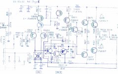
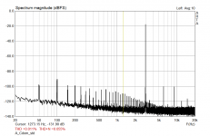
4. Did you try to include a output-stage including Miller Cdom variant? I did this in a Yamaha AX592 and it works fine. In this mod, the Cdom of 100pF is split into two serial 220pF, and the midpoint is connected to the power device's emitters resistors's common connection point by a 1k4 resistor. Result: See the two Arta graphs.
5. By which criteria did you choose the different emitter degeneration's resistors values of the IPS, CM and the VAS? E.g. is there a "sweet spot" to do so? Depending on the Ic's of the IPS, the CM and the VAS I arbitrarily chose to set them for a compromise 1:10 ratio of re/R_degen. I am shure there must be better criteria than this rather irrational magic of decimal values ...
I hope not to bother you too much with these questions!
1. And most important: Very interesting thread!
2. Some time ago you published a composite VAS including a third T3. In your example, T3 acts at the same time as the buffer for T2 and also as a "current splitter" by T3's VBE paralleled by the 330 ohm resistor. In your example, this might set the IC for T2 as some 0.7/330=2.1mA. I first saw this option in D.Self's power amplifier book, and then tried it in a Yamaha AX590 VAS modification. But that lead to some oscillation, so I discarded it again. My first question then: Do you still use this theoretically elegant modification, e.g. is it successfully long-term stable/safe in your Rotel mod's?
3. Did you try to include improved CM's in your modifications? I am especially interested in the EFA current mirror as published in Samuel Groner's 2011 comments on Self's designs. I have not tried this one out, and I am wondering why I am not able to find any implemented and working examples of such avariant when searching by Google. Does this EFA CM variant come along with serious drawbacks in practice?
4. Did you try to include a output-stage including Miller Cdom variant? I did this in a Yamaha AX592 and it works fine. In this mod, the Cdom of 100pF is split into two serial 220pF, and the midpoint is connected to the power device's emitters resistors's common connection point by a 1k4 resistor. Result: See the two Arta graphs.
5. By which criteria did you choose the different emitter degeneration's resistors values of the IPS, CM and the VAS? E.g. is there a "sweet spot" to do so? Depending on the Ic's of the IPS, the CM and the VAS I arbitrarily chose to set them for a compromise 1:10 ratio of re/R_degen. I am shure there must be better criteria than this rather irrational magic of decimal values ...
I hope not to bother you too much with these questions!
Attachments
Last edited:
4. Did you try to include a output-stage including Miller Cdom variant? I did this in a Yamaha AX592 and it works fine. In this mod, the Cdom of 100pF is split into two serial 220pF, and the midpoint is connected to the power device's emitters resistors's common connection point by a 1k4 resistor. Result: See the two Arta graphs.
Forget this one and sorry for it ... I somehow missed your post #509 relating to this precise question.
- Home
- Amplifiers
- Solid State
- Improve a Rotel amp THD by 20dB!