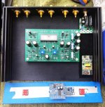
Finally received all the parts I need and getting ready to wire the Korg pcb together with the Academy Audio volume control. I have included an SMPS filter that I received from Monk55, and a +/- 12V power supply for the volume control.
The volume control pcb interconnect points are inline and on .1" centers. I'm looking for ways to reduce wiring, especially to those VCU pads, and would like some advice on ground connections.
It seems to me that all grounds, without exception, eventually wind up connected to the pcb trace that runs around the outside of the board. Given that fact, is there a need for all the ground wires related to the inputs and the output to all follow the hot leads they are associated with, or can they be "shortest distance" connected to the nearest grounding pad on the pcb?
And, can the VCU signal grounds be simply connected to the pcb ground at the front of the pcb with the input grounds connected to the pcb ground at the back of the pcb?
As for the power ground, it seems to me that it needs to run to the front panel to power the LED (and, in my case, the +/- 12V supply) but does it also have to run all the way back per the switch wiring instructions? Can the ground simply be used as it comes into the chassis -- through the SMPS filter -- then to the pcb?
Scratching my head over how this might affect signal quality.
Attachments
Last edited:
Academy just posted a tech note that describes their approach: App Notes | academyaudio
I'll be trying this out, hopefully this week.
I'll be trying this out, hopefully this week.
Academy just posted a tech note that describes their approach: App Notes | academyaudio
I'll be trying this out, hopefully this week.
Very interested to hear if there is an audible improvement. I'm starting out with a simple 24V -> +/- 12V converter, not sure how it will sound.
Last edited:
Looking good wapo...draw out your ground scheme to find shortest path. Insure you scratch through the anodizing for one of the standoffs.
Nice wapo, I received my academy audio board and display a couple of days ago and now trying to find time to lay up the enclosure I'm fabbing for it. Is that the Muses power supply in the bottom right of your photo?
Finally received all the parts I need and getting ready to wire the Korg pcb together with the Academy Audio volume control. I have included an SMPS filter that I received from Monk55, and a +/- 12V power supply for the volume control.
The volume control pcb interconnect points are inline and on .1" centers. I'm looking for ways to reduce wiring, especially to those VCU pads, and would like some advice on ground connections.
It seems to me that all grounds, without exception, eventually wind up connected to the pcb trace that runs around the outside of the board. Given that fact, is there a need for all the ground wires related to the inputs and the output to all follow the hot leads they are associated with, or can they be "shortest distance" connected to the nearest grounding pad on the pcb?
And, can the VCU signal grounds be simply connected to the pcb ground at the front of the pcb with the input grounds connected to the pcb ground at the back of the pcb?
As for the power ground, it seems to me that it needs to run to the front panel to power the LED (and, in my case, the +/- 12V supply) but does it also have to run all the way back per the switch wiring instructions? Can the ground simply be used as it comes into the chassis -- through the SMPS filter -- then to the pcb?
Scratching my head over how this might affect signal quality.
Rather than calling both the chassis and boards "ground" I'd refer to them as the circuit's return path or the chassis/earth ground, because they are different but related.
For the return path for each of the + wires (i.e.: the - wire), I'd advise keeping them together as a pair AND twisting the wires together as you have seen in the many build examples. This avoids the usual issues with running parallel runs and the usual induction issues. It also ensures a common, low impedance return ground point (i.e.: the ground plane on the board) so that you avoid ground loops.
6L6 set this up conveniently with the B1K kit as he used pre-twisted cat6 ethernet cable for the project. I'd advice you follow his example. If you don't go that route, it is advisable to twist each pair along its route, and also try to keep each pair away from other pairs that it is near.
--Tom
Nice wapo, I received my academy audio board and display a couple of days ago and now trying to find time to lay up the enclosure I'm fabbing for it. Is that the Muses power supply in the bottom right of your photo?
That part is
Digikey PART: 1866-3622-ND
MFG : MEAN WELL USA Inc. / NSD10-12D15
If I need to, I'll add an ultra-quiet linear supply downstream of the Mean Well but hope it won't be necessary. I have intentionally made it easy to remove & replace the two power-related boards by laying down a strip of adhesive-backed velcro along the edge of the chassis and putting small pieces (that hold ferociously) on the bottom of the boards. Insulates and holds in place and I can upgrade at any time with zero fuss. This must be making all the purists shudder in dismay! 🙂
Last edited:
Plate voltages drifting lower?
I have my B1 running since X'mas last year.
Today, I opened it up and checked the plate voltages. I had them set to 9.5v like 2 months ago. Today, they read 8.6x volts. So I set it again to 9.5v. This is the second adjustment in 3 months.
Has anyone experienced the same issue?
PS - can the PCB be revised to use a 10 turns trimpot instead of a single turn one? It is hard to get 9.5v precisely with a single turn pot.
Mods I've done in my B1
Over the last 3 months, I've the following mods added to my B1:
1. Changed the six Nichicon FW signal coupling caps to Nichicon Muse ES.
2. Replaced the volume knob with TKD (same 50K ohm pot from Parts Connexion).
3. Replaced the 24v SMPS with a LPS I bought from eBay. It is one of those "Studer900" LPS with a 30VA R-Core transformer.
The Muse ES does offer more balanced sound and a more revealing mid-range. They do require 2+ weeks to break-in, and I got loss of bass sometime in week 2. I think if 6L6 is putting together more kits for sales in the future, I don't see why we're still using the FW caps.
The TKD volume knob does remove some sibilance in the sound which is a surprise to me. It is able to render some nuances that I haven't heard before.
The eBay Studer900 supply is a total surprise to me. I think these guys have borrowed some kind of regulation circuit from a Studer mixing console. Anyway, the supply is remarkably good sounding for the amount I paid. It has a 30VA R-Core transformer and is already using Schottky rectifiers. The only thing I've to replace in the LPS is the Chinese made RM cap with a Panasonic TSHA cap.
The important thing to know is that it is not the DC side of the SMPS that is not good enough. The 3-stage RC circuit in B1 is effective in reducing the noise for any SMPS. It is the noise a SMPS dumps to the AC side and that noise is picked up from sensitive audio equipment (ie: your DAC). I have SMPS powering other devices that are not in the audio chain, but happen to share the same wall outlet. Just by unplugging these SMPSes have improved the sound - wider and more holographic sound stage and more analog sound.
So I'm in the process of eliminating all SMPS, and replacing them with LPS using a simple LT1083 regulator. That should be more than good enough for this purpose. Some eBay sellers are offering 10-15% off LPS sales until March 24th. So I picked up 3 more 50VA R-Core LPS for $89 each including shipping.
@ Kuro
With light pin bend you can stuff new multiturns trimmer into the PCB without addition modifications.
I have done this my self and yes precision adjustements are much easier
With light pin bend you can stuff new multiturns trimmer into the PCB without addition modifications.
I have done this my self and yes precision adjustements are much easier
The Muse ES does offer more balanced sound and a more revealing mid-range. They do require 2+ weeks to break-in, and I got loss of bass sometime in week 2.
In my experience, 99% of "break-in" happens between your ears. I have 3 B1K with three different capacitors and the only one I can hear a very slight difference in has Toshiba instead of Fairchild Jfets, and is on a slight different PCB revision.
I think if 6L6 is putting together more kits for sales in the future, I don't see why we're still using the FW caps.
Here are the exact reasons the ES will never be in the kits -
1) Nelson did not specify a bipolar capacitor in these positions.
2) They are not easily available in the quantity required for a kit run.
3) The ES are 4x as expensive as the FW in quantity, and at that price I'd rather have FG, because the jacket and name looks cooler. 🙂 (but are also hard to get in quantity)
4) SYclotron Audio | Why are people obsessed with coupling caps?
The TKD volume knob does remove some sibilance in the sound which is a surprise to me. It is able to render some nuances that I haven't heard before.
Not surprised, the TKD pots are absolutely fantastic.
 They also cost $100USD, so one would hope they are good!!
In my experience, 99% of "break-in" happens between your ears. I have 3 B1K with three different capacitors and the only one I can hear a very slight difference in has Toshiba instead of Fairchild Jfets, and is on a slight different PCB revision.
Here are the exact reasons the ES will never be in the kits -
1) Nelson did not specify a bipolar capacitor in these positions.
2) They are not easily available in the quantity required for a kit run.
3) The ES are 4x as expensive as the FW in quantity, and at that price I'd rather have FG, because the jacket and name looks cooler. 🙂 (but are also hard to get in quantity)
4) SYclotron Audio | Why are people obsessed with coupling caps?
Not surprised, the TKD pots are absolutely fantastic.
I'm no going to argue with you on component break-in. It is a dead horse. Some people hear them some don't. It depends on the resolution of your system and also the kind of music you played. Less if it is just pop music. More if you have music with lots of reverbs and harmonic decays.
Just because Nelson Pass did not specify non-polar caps for signal coupling does not mean we can't use them. People use film caps for signal coupling all the time.
I just did a search on Mouser, Muse ES 10uF 25v, 977 pieces in stock. If you buy a 500 pieces, it is $0.211 a piece. You're right that there is no 10uF 50v in stock. But 25v for signal coupling is more than sufficient in our case. The Nichicon FG 10uF 50v supplied in my kit is $0.152 for the same quantity purchased. So it is not that much more in price.
People throw measurements out all the time, claiming there is no difference. It is just like comparing 2 different DACs with frequency domain measurements, they both measured excellent yet they can sound very different. Why? It is because they are not measuring right. It should have been a time domain measurement. This is where differences are heard.
TKD is for those who wants the last little bit. It is still not a night and day difference, subtle everywhere, I must say. But to some, it is significant enough.
Last edited:
Here's the thing:
It's entertainment, not dialysis.
Whether or not there is a difference and whether or not you can hear it is part
of the enjoyable experience that is DIY.
If there is no difference at all, that does not mean it wasn't a successful experiment.

It's entertainment, not dialysis.
Whether or not there is a difference and whether or not you can hear it is part
of the enjoyable experience that is DIY.
If there is no difference at all, that does not mean it wasn't a successful experiment.
I have been fortunate to have been able to audition Five Variants of the KB1,
Three Have been used in my own system.
There has been Models with Black Gate Cap's, as well as other Cap's and Bypass Cap's used on the Builds.
There has additionally been Dual Mono Volume Control Pot's, Stepped Att's and a Promethius TVC.
When Lock down is done, there will become available Two other KB1's to
audition, One will be a Balanced Design and the other that will be mine, built on a uncommon PCB, that will have a Bespoke Hand Built Stepped Att' .
IMV , The KB1 supplies many good experiences and valued memories in all build guises when auditioned.
Additionally, the Entertainment Value capable from the KB1 in any system I have heard it in is through the roof.
Nelson is absolutely correct in his encouragement to enjoy this Pre Amp.
Success!
After hours of problem solving, replacing capacitors, checks for cold solder, three 9v diodes...Success! The Korg B1 Nutube complements my ACA monoblocks perfectly. I was worried the whole affair may also not complement my DIY falcon LS3/5As. Not to worry, they sing. THANK YOU Papa Pass. Can't wait for burning amp.😀
After hours of problem solving, replacing capacitors, checks for cold solder, three 9v diodes...Success! The Korg B1 Nutube complements my ACA monoblocks perfectly. I was worried the whole affair may also not complement my DIY falcon LS3/5As. Not to worry, they sing. THANK YOU Papa Pass. Can't wait for burning amp.😀
Attachments

Since the parts package was not available at diyaudio when I decided to build the Korg, I've been getting my parts from other sources.
Latest issue is, I used a spare generic LED and a 1K0 resistor to do the power light on the front panel. It works, but my LED is too bright by far, and the 1K0 resistor is pure guess. Can someone tell me the part number for the green LED (which I assume isn't too bright for the purpose), and confirm the resistor value?
I've got the kit done, voltages check out. I'm going to ignore the Academy Audio volume control I have installed until I can confirm proper operation of the preamp board -- using an outboard LDR volume control for the moment before the input jacks, hope to listen today.
Last edited:
just take 1K for every PSU Volt
so, if you feed LED from 12V , anything between 10K and 12K would work
don't be scared to increase or decrease value of resistor, to set brightness to your liking
so, if you feed LED from 12V , anything between 10K and 12K would work
don't be scared to increase or decrease value of resistor, to set brightness to your liking
- Home
- Amplifiers
- Pass Labs
- B1 with Korg Triode