BC549 and BC559 are good substitutes. They are only 30V vs 45V, they're cascoded so it doesn't matter.
VI limiters. Or short circuit detection on board.
Good idea , I even go halfway and add a jack for monitoring the
2 end - pair's ( P/N) emitter resistors.
Did this on the Slew for Jwilhelm's protection with the SS relays.
Could even add the SS relay pads on the output side of the board.
But it would be easier to just use an outboard unit.
Three reasons .....
- they sell a protecting pcb in the store.
- some might not want it.
- some might want either a cheap Ebay unit or something far better.
This is why I even left out the fuses on this model.
Jwilhelm even has a low Rds MOSFET rail cutoff option for the power.
Some "purists" niether like fuses or VI limiters. They feel soiled by them.
I personally would like the more advanced external solution.
OS
It would be a good idea to have somewhere to anchor the driver heat sink to. Those big devices are easy to hit and mangle.
See below , use the existing UMS board hole.
Hey J , see the 5 jumpers from both the main HS Vbe and the P/N channel
main basestopper traces.
Both the cancelling 6mm rail traces and the double sided output rail do not allow me to "snake" any trace under/ or over them.
Any ideas ??
OS
Attachments
Last edited:
The double sided rails can be a pain! I just put the temp sensing transistor under the main board on the NS Amp. Can you use one of the board mounting screw hole instead? Could you swap Q103 and Q104's job roles? Q103 is connected with resistors, they could replace the jumpers.
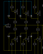
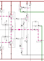
We came up with a better overcurrent detection scheme. Instead of just connecting to one positive and one negative emitter resistor we connect to them all with small diodes. The current sensor will see the highest current device that way so if there's a current hog it will catch it.
We came up with a better overcurrent detection scheme. Instead of just connecting to one positive and one negative emitter resistor we connect to them all with small diodes. The current sensor will see the highest current device that way so if there's a current hog it will catch it.
An even simpler fix might be to run the power rails on the other side of the output transistors.
Hi, OStripper.
I really like this amp. A great example of a blameless amplifier with lots of attention to detail. This one is going to measure and sound great.
Of course, I have some suggestions. They are just that. Take them or leave them.
1) Biasing the input cascode bases. I would short R10 and then replace R5 with 3 or 4 diodes. I like to see low impedance on a cascode base. Tieing Q7 base directly to the LTP emitters won't hurt anything. You don't really even need Q7. You could just tie 4 diodes between the LTP emitters and the cascode bases, and raise the tail current to produce the extra. I've done that lots of times.
2) I think you should leave an option for a small resistor in series with C4 to help eke out a bit more GBW and PM. There is a possibility of cancelling a pole with the feedforward zero, if you add the resistor.
3) I've was really impressed with the results recently when I flipped the pre-driver upside down into a diamond configuration. That one's purely a matter of personal preference, I think.
4) A 2 to 5 pF in parallel with the 22K feedback resistor can be another enhancement to PM and GM, letting you eke out some more GBW.
5) I'd suggest adding two-pole compensation, but now I'm getting tweaky.
The double sided rails can be a pain! I just put the temp sensing transistor under the main board on the NS Amp. Can you use one of the board mounting screw hole instead? Could you swap Q103 and Q104's job roles? Q103 is connected with resistors, they could replace the jumpers.
We came up with a better overcurrent detection scheme. Instead of just connecting to one positive and one negative emitter resistor we connect to them all with small diodes. The current sensor will see the highest current device that way so if there's a current hog it will catch it.
Show me a picture of that ...
Q103 just adjusts the main Vbe's ratio.
The main Vbe (Q104) , does the major negation of the main outputs thermal Vbe change.
OS
Hi, OStripper.
I really like this amp. A great example of a blameless amplifier with lots of attention to detail. This one is going to measure and sound great.
Of course, I have some suggestions. They are just that. Take them or leave them.
1) Biasing the input cascode bases. I would short R10 and then replace R5 with 3 or 4 diodes. I like to see low impedance on a cascode base. Tieing Q7 base directly to the LTP emitters won't hurt anything. You don't really even need Q7. You could just tie 4 diodes between the LTP emitters and the cascode bases, and raise the tail current to produce the extra. I've done that lots of times.
2) I think you should leave an option for a small resistor in series with C4 to help eke out a bit more GBW and PM. There is a possibility of cancelling a pole with the feedforward zero, if you add the resistor.
3) I've was really impressed with the results recently when I flipped the pre-driver upside down into a diamond configuration. That one's purely a matter of personal preference, I think.
4) A 2 to 5 pF in parallel with the 22K feedback resistor can be another enhancement to PM and GM, letting you eke out some more GBW.
5) I'd suggest adding two-pole compensation, but now I'm getting tweaky.
Hmmm ...
1 - I like eliminating R10. This was a remnant of earlier designs.
No effect on THD.
Q7 just makes the cascode reference independant from the LTP's. (buffer)
Using 4 diodes would make the Q1/2 run at 3V Vce ,current mirror would
see much more voltage.
Lower Z on the cascode from Q7 is a good idea. I will go half way and
use R5- 10k and R6 -15K.
In the real world , one builder tested this design at 60v p-p. 5-7 ppm @ 20k.
Consistantly. with no TMC.
2- easy to do that ... I need to simulate that.
3 - show a example of that.
4 - a little lead compensation ... I actually had that as a Badger option.
5 - yeah .. Two pole , like the badger. This design beats it without TMC.
I should see what TMC can do.
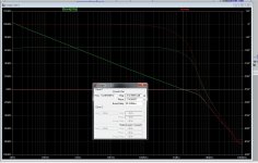
Wow !! , never tried TMC on this triple !!! (below 1) that is 100v p-p/ 4R /20K.
Bode (below 2)with 330p/68p two pole and output FB at 2.2K ... (below 2) No peak at UG , Nice sim !!
Enough margin... 1.6 mhz UG - aggressive - like a Wolverine.
OS
Attachments
Last edited:
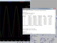
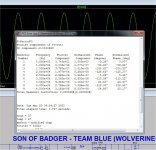
Whoa !!
Never got readings like this ... (below).
2ppm LF to 2Khz / WAY ... sub- ppm 3K to 15K / up to 4ppm 20k as the amp
runs out of gain margin. Wow - I hit 10ppm at 33Khz.
Stunning results.
Yes ... fixed the Vbe layout deal - Thanks Jwilhelm (layout master) !!
Found a UMS hole right near the driver cluster.
-- (below 2)
J , what SIP connectors do you use for the VZ amp modules ??
does Mouser have them ?
OS
Attachments
There are lots of female headers to choose from at Mouser. I usually use Molex version. 538-90147-1108 https://www.mouser.ca/Connectors/He...yzv7x1Z1z0xbxoZ1z0xby7&Keyword=header&FS=True
I've attached a picture of our new overload detection scheme. This will send the detection circuit the highest voltage drop readings from all of the output devices instead of just one pair. We tune the trip point on an optoisolator to match maximum peak output current to signal the microcontroller.
I've attached a picture of our new overload detection scheme. This will send the detection circuit the highest voltage drop readings from all of the output devices instead of just one pair. We tune the trip point on an optoisolator to match maximum peak output current to signal the microcontroller.
Attachments
Last edited:
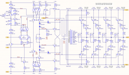
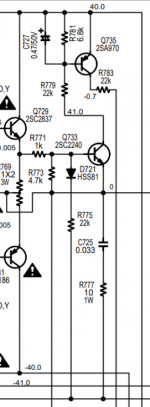
Look at the schematic below for examples of 1) and 3).Hmmm ...
1 - I like eliminating R10. This was a remnant of earlier designs.
No effect on THD.
Q7 just makes the cascode reference independant from the LTP's. (buffer)
Using 4 diodes would make the Q1/2 run at 3V Vce ,current mirror would
see much more voltage.
Lower Z on the cascode from Q7 is a good idea. I will go half way and
use R5- 10k and R6 -15K.
In the real world , one builder tested this design at 60v p-p. 5-7 ppm @ 20k.
Consistantly. with no TMC.
3 - show a example of that.
The bias leg on the left shows my preferred way of biasing an input cascode. I'm using IR LEDs instead of diodes, but the idea is the same. Those IR LEDs are 1.25V each at 2mA. So, that's about like 4 regular diodes.
My EF triple shows an example of the flipped-over pre-driver. The pre-driver runs at nearly constant current, so it's current does not have to be very high. Flipping the pre-driver gives you another VBE at each end of the voltage swing. It also seemed to give me slightly lower OPS distortion.
You are beating me on THD. I'm seeing at 100W about 3ppm up to about 2 kHz, and rising to 15 ppm at 20 kHz. I'm still working on lowering THD. As I said before, nice work. I really like your Wolverine amp.Wow !! , never tried TMC on this triple !!! (below 1) that is 100v p-p/ 4R /20K.
Bode (below 2)with 330p/68p two pole and output FB at 2.2K ... (below 2) No peak at UG , Nice sim !!
Enough margin... 1.6 mhz UG - aggressive - like a Wolverine.
Attachments
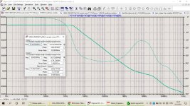
Wow !! , never tried TMC on this triple !!! (below 1) that is 100v p-p/ 4R /20K.
Bode (below 2)with 330p/68p two pole and output FB at 2.2K ... (below 2) No peak at UG , Nice sim !!
Enough margin... 1.6 mhz UG - aggressive - like a Wolverine.
OS
OS, this bode plot does not look like two pole compensation.🙁
This is what I've got with my OITPC compensation (kind of TPC).
Attachments
Last edited:
Hi OS,
Dadod is right.
Phase in TPMC should dip way below 90 degrees, and then come back close to 90 degrees before you reach the loop gain 0dB crossing. I can see that your phase dips very slightly below 90, but there is hardly any extra correction at all.
Dadod is right.
Phase in TPMC should dip way below 90 degrees, and then come back close to 90 degrees before you reach the loop gain 0dB crossing. I can see that your phase dips very slightly below 90, but there is hardly any extra correction at all.
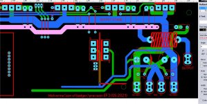
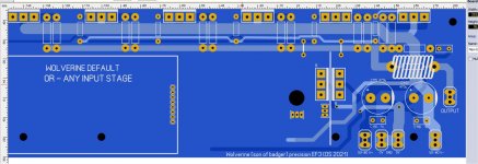
PCB Layout suggestion
Why are you not use this example pcb board for this design? Output 3EF on left and right side, drivers on main heatsink and Vbe drivers on left side of heatsink and Vbe for output stage on right side of heatsink. Upper center put electrolytics with regulated psu jacks for input and vas stage.
16-27-14-attachment — ImgBB
I'm looking forward to seeing how this one turns out. I have successfully built Honey Badger v2.4, and a Slewmaster with the Spooky leach front end. Absolutely no trouble with either amp, even running some demanding loads like Magnepans.
Protection should be considered even if it's Not VI limiters. I agree dc detect can be on another board. But even basic short circuit detect is common on all commercial amplifiers.
How effective they are can be argued but i think it's a clear consideration that should be made, even if it's just detection and not the actual protection board.
Attached detect from Yamaha and Marantz.
How effective they are can be argued but i think it's a clear consideration that should be made, even if it's just detection and not the actual protection board.
Attached detect from Yamaha and Marantz.
Attachments
Would there be a problem to hardwire the VBE from that posistion? I for one would rather have the VBE as close as posible to the outputs.Whoa !!
Never got readings like this ... (below).
2ppm LF to 2Khz / WAY ... sub- ppm 3K to 15K / up to 4ppm 20k as the amp
runs out of gain margin. Wow - I hit 10ppm at 33Khz.
Stunning results.
Yes ... fixed the Vbe layout deal - Thanks Jwilhelm (layout master) !!
Found a UMS hole right near the driver cluster.
-- (below 2)
J , what SIP connectors do you use for the VZ amp modules ??
does Mouser have them ?
OS
If the board is mounted properly with the output devices mounted to the lower side of the heatsink there isn't really any advantage to having the VBE transistor located closer to the output devices. We've tested this many times in the Slewmaster amp. This is the best thermal tracking design I've ever seen.
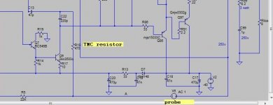
I think Os did not connect TMC resistor after the probe as it should be as in attached picture.
I bet you are right. Wired correctly for operation, but not for the Bode plot.
- Home
- Amplifiers
- Solid State
- DIYA store "Wolverine" (Son of Badger) .... suggestions ??