Can you please explain why the figure-8 connector is singled-out as being unreliable? I've never had any problems with it. Any cable/connection can be unreliable if it's been subject to abuse - including the IEC. C13/14.
usually a socket designed for high voltage and high current is the better one
Of course for a preamp or dac that do not need a earth connection and consume 100-200 mA even the figure 8 can be fine
But above 230V/2A figure 8 is not recommended ?
Depending on the execution of course Not all figure 8 are equal ... i like the ones from Apple for instance They exudes quality Also the attached cables Apple is apple You pay but you get
Last edited:
"But above 230V/2A figure 8 is not recommended ?"
It should be fine for 230V, so long as the connections are manufactured in accordance with the country's electrical specifications and are of good quality. It's a relatively common power connection.
It should be fine for 230V, so long as the connections are manufactured in accordance with the country's electrical specifications and are of good quality. It's a relatively common power connection.
Modding an IEC Class II appliance to a Class I appliance is not recommended for the following reason:
All touchable metal parts of the enclosure must be connected to the protective earth. The IEC Class II appliances are not designed with continuity between the external metal parts. The external metal parts are double insulated from the mains instead. You must connect the top, bottom, sides etc. to the PE individually, but this is unpractical and unreliable.
All touchable metal parts of the enclosure must be connected to the protective earth. The IEC Class II appliances are not designed with continuity between the external metal parts. The external metal parts are double insulated from the mains instead. You must connect the top, bottom, sides etc. to the PE individually, but this is unpractical and unreliable.
"But above 230V/2A figure 8 is not recommended ?"
It should be fine for 230V, so long as the connections are manufactured in accordance with the country's electrical specifications and are of good quality. It's a relatively common power connection.
Thanks a lot. 🙂
Modding an IEC Class II appliance to a Class I appliance is not recommended for the following reason:
All touchable metal parts of the enclosure must be connected to the protective earth. The IEC Class II appliances are not designed with continuity between the external metal parts. The external metal parts are double insulated from the mains instead. You must connect the top, bottom, sides etc. to the PE individually, but this is unpractical and unreliable.
Hi ! thanks a lot for the valuable advice. But if i to leave the earth pin on the panle socket non connected i will have problem the same ? 🙄
Again ... i would make units with captive power cords illegal ... 😡
Also because i like to play with different power cords 😱🙁 just a little ...
"Figure 8" are fine for low power devices but we use metal casings most of the time to prevent stray in/stray out of HF/RF. Metal casings should be connected to PE for safety (it helps for shielding). Now regulations here tell that devices under 5VA don't need PE...
So I designed many small PSU's with figure 8 and no PE and metal casings. However with modern transformers leakage to the casing can be very high. With recently produced small toroids I can have easily 70 to 90V leakage at a very small current. That is why I changed to having IEC connectors with casing connected to PE. Audio GND is then referenced to PE with 100 Ohm. This to avoid damage to sensitive equipment when plugging in the PSU as the occurring AC leakage of course is at both + and -.
That would be plain eh... unwise. When refusing to have PE then choose the 2 pin IEC version and 2 wire cables. Best, safest and legal however is of course to use the 3 pins version and connect chassis to PE. Absolute worst of ideas is using 3 wire cables, 3 pin IEC connectors and then leave PE not connected. The situation then seems safe but in reality it totally isn't. If you love your children and partner I would advise not to do this.
People who do such practices are the same that complain about a tickling feeling when they touch the casings 🙂 Not knowing that mains filters in SMPS like in pc's have filter caps connected from both L and N to PE. This PE connection is not there so the middle point of these caps is now half the mains voltage. This is 115V on the casing in reality and enough to be unpleasant when people are standing on the floor as humans usually do....
So I designed many small PSU's with figure 8 and no PE and metal casings. However with modern transformers leakage to the casing can be very high. With recently produced small toroids I can have easily 70 to 90V leakage at a very small current. That is why I changed to having IEC connectors with casing connected to PE. Audio GND is then referenced to PE with 100 Ohm. This to avoid damage to sensitive equipment when plugging in the PSU as the occurring AC leakage of course is at both + and -.
But if I leave the PE pin on the panel socket not connected I will have problem the same ? 🙄
That would be plain eh... unwise. When refusing to have PE then choose the 2 pin IEC version and 2 wire cables. Best, safest and legal however is of course to use the 3 pins version and connect chassis to PE. Absolute worst of ideas is using 3 wire cables, 3 pin IEC connectors and then leave PE not connected. The situation then seems safe but in reality it totally isn't. If you love your children and partner I would advise not to do this.
People who do such practices are the same that complain about a tickling feeling when they touch the casings 🙂 Not knowing that mains filters in SMPS like in pc's have filter caps connected from both L and N to PE. This PE connection is not there so the middle point of these caps is now half the mains voltage. This is 115V on the casing in reality and enough to be unpleasant when people are standing on the floor as humans usually do....
Last edited:
"Figure 8" are fine for low power devices but we use metal casings most of the time to prevent stray in/stray out of HF/RF. Metal casings should be connected to PE for safety (it helps for shielding). Now regulations here tell that devices under 5VA don't need PE... So I designed many small PSU's with figure 8 and no PE and metal casings
Hi ! thanks a lot and this exacting the norm. Just to make an example ... most of dvd/BR players have smps and figure 8 sockets.
I really do not understand why replacing it with a IEC socket and grounding the metal enclosure should be dangerous. I cannot understand.
I can understand that figure 8 standard is cheaper, easier to use.
I think i will use the IEC C14 plug type on captive cords ... and done with that.
i really have to study more .. by the way sometime i have noticed that Audio GND taken on rca outputs and PE are at the same potential in some units. The tester makes the beep ... like a shortcircuit. Is this bad ? should i put some 100ohm resistor somewhere ?... However with modern transformers leakage to the casing can be very high. With recently produced small toroids I can have easily 70 to 90V leakage at a very small current. That is why I changed to having IEC connectors with casing connected to PE. Audio GND is then referenced to PE with 100 Ohm. This to avoid damage to sensitive equipment when plugging in the PSU as the occurring AC leakage of course is at both + and -.
i will do like this in case i put a iec panel socketThat would be plain eh... unwise. When refusing to have PE then choose the 2 pin IEC version and 2 wire cables. Best, safest and legal however is of course to use the 3 pins version and connect chassis to PE.
there is just one child in my house ... meAbsolute worst of ideas is using 3 wire cables, 3 pin IEC connectors and then leave PE not connected. The situation then seems safe but in reality it totally isn't.
If you love your children and partner I would advise not to do this.

People who do such practices are the same that complain about a tickling feeling when they touch the casings 🙂 Not knowing that mains filters in SMPS like in pc's have filter caps connected from both L and N to PE. This PE connection is not there so the middle point of these caps is now half the mains voltage. This is 115V on the casing in reality and enough to be unpleasant when people are standing on the floor as humans usually do....
Thank you very very much again. In case i will decide for the iec mod i will use the PE pin to ground the chassis for sure. Better to be safe than sorry
And if the units will be lower consumption i could even put just a dc socket and use an external psu to avoid to enter in the chassis with high voltages.
Some dvd player already use an external smps like the laptop. I like this idea to keep the high voltages out of the units that can be touched.
These are simple matters but then again not so simple when safety is concerned. Many matters have been thought out by clever people and then they were regulated. This led to Class I and Class II devices which is way too complicated to explain in a few sentences. To laymen things seem simple and are often not 100% understood as apparent simple trivial things get little to no attention....
Let's make it both safe and working OK. In DIY this means Class I. So a metal chassis should be connected to the PE pin according a predefined way of mounting with bolt, nut and certain washers. Chassis now will be connected to PE and a loose L wire will cause the breaker to switch off or the fuse to melt. The person touching the casing will never be electrocuted which is OK 🙂
Now audio GND.... This is the secondary side of the mains transformer/PSU and the common GND for the audio circuits. In some areas Audio GND is connected to PE as well but when doing this one almost has a a guaranteed ground loop en therefor hum. Normally we are in this hobby for best possible results so hum is not wanted.
A way to eliminate ground loops is to have chassis connected to PE but to "lift" audio GND with a 10 Ohm resistor, a diode bridge, a CL60 thermistor etc. This will reference Audio GND within reasonable limits to PE but without the negative side effects. We can repeat this in every source device and have only the power amplifiers Audio GND connected directly to PE. There now is only 1 point where Audio GND is connected with milliOhm impedance to PE. No ground loops and still safe and good audio results.
* please remember: any ready made device that has a 3 pin IEC inlet will need to be connected to a wall outlet with PE. When you pay attention you will see many situations at family, friends etc. where this is not the case....the tickling feeling issue....
Last edited:
These are simple matters but then again not so simple when safety is concerned. Many matters have been thought out by clever people and then they were regulated. This led to Class I and Class II devices which is way too complicated to explain in a few sentences. To laymen things seem simple and are often not 100% understood as apparent simple trivial things get little to no attention....
Let's make it both safe and working OK. In DIY this means Class I. So a metal chassis should be connected to the PE pin according a predefined way of mounting with bolt, nut and certain washers. Chassis now will be connected to PE and a loose L wire will cause the breaker to switch off or the fuse to melt. The person touching the casing will never be electrocuted which is OK 🙂
Thanks ! perfect. I fix this in my mind very clearly. I wonder why they have invented this class II ... is it really needed ? any earthed appliance should be safer by design Strange To have a live wire inside with high voltage is always a risk ... For instance a dvd player. Usually they have inside smps at very high voltage.
Now audio GND.... This is the secondary side of the mains transformer/PSU and the common GND for the audio circuits.
In some areas Audio GND is connected to PE as well but when doing this one almost has a a guaranteed ground loop en therefor hum.
Normally we are in this hobby for best possible results so hum is not wanted.
A way to eliminate ground loops is to have chassis connected to PE but to "lift" audio GND with a 10 Ohm resistor, a diode bridge, a CL60 thermistor etc.
This will reference Audio GND within reasonable limits to PE but without the negative side effects. We can repeat this in every source device and have only the power amplifiers Audio GND connected directly to PE.
There now is only 1 point where Audio GND is connected with milliOhm impedance to PE. No ground loops and still safe and good audio results.
* please remember: any ready made device that has a 3 pin IEC inlet will need to be connected to a wall outlet with PE. When you pay attention you will see many situations at family, friends etc. where this is not the case....the tickling feeling issue....
another rule to print in my brain. However the audio ground issue ... i have to study that Every time i checked with the tester the result has been always a beep ... 🙁
Thanks a lot again for the kind and precious advice.
Class II can only be built by a manufacturer and then tested by a certified lab. No DIYer can reach that level with just 1 device in practice. It is no coincidence that class II devices are very often made of plastic which AFAIK 😉 does not conduct electricity.
Ground lifted with 10 Ohm resistor, diode bridge, CL60 thermistor.... also give a beep I think. Using the beep function is for simple and fast conclusions, please use the resistance setting and measure real Ohms for true measurements. Even yesterday I made a mistake in a device where the PSU was lifted in the negative side of the PSU but still was connected with relatively low resistance. You will not see that when using the beep. As usual convenience does not make things really better.
However the audio ground issue ... i have to study that Every time i checked with the tester the result has been always a beep ... 🙁
Thanks a lot again for the kind and precious advice.
Ground lifted with 10 Ohm resistor, diode bridge, CL60 thermistor.... also give a beep I think. Using the beep function is for simple and fast conclusions, please use the resistance setting and measure real Ohms for true measurements. Even yesterday I made a mistake in a device where the PSU was lifted in the negative side of the PSU but still was connected with relatively low resistance. You will not see that when using the beep. As usual convenience does not make things really better.
Last edited:
Further to my comments about figure-8 connectors being OK with 230V. In my mind I was referring to the IEC C7/C8 coupler, which if properly manufactured should meet your country's electrical standards.
There are lots of other connectors which are designed for two wires but can't take high voltages (eg. the round connectos found on wallwarts for low voltages).
If in doubt, buy from a reputable electronics/electrical store, where they will be able to refer to the product's spec. sheet to verify the voltages it is designed for. If you are ever in doubt, use a connector that's rated for higher voltages than you intend to use, but never a lower voltage rating.
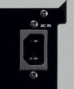
All my Yamaha products use a 2 pin IEC as shown in the pic. The lead supplied also has only 2 prongs for the wall outlet.
The only commercial product I have that uses 3 pins is a Cambridge CXN. Also I do use 3 pins on my DIY amps with chassis grounded to earth.
The only commercial product I have that uses 3 pins is a Cambridge CXN. Also I do use 3 pins on my DIY amps with chassis grounded to earth.
Attachments
Class II can only be built by a manufacturer and then tested by a certified lab. No DIYer can reach that level with just 1 device in practice. It is no coincidence that class II devices are very often made of plastic which AFAIK 😉 does not conduct electricity.
Thanks lot again. This starts to worry me a lot. Let's say that i have in my hands a very cheap chinese amp with just a two pins plug and with a Class II mark just above where the power cord enters the metallich chassis.
Could it be the case that it is not a "true" Class II device ? in my basic ming i would make mandatory to earth any metallic chassis. Better be safe than sorry. If the case is plastic ok ... but this is more an exception than the norm. For very low consumption devices i like also the external psu solution.
thank you very much I will do for sure from now on.Ground lifted with 10 Ohm resistor, diode bridge, CL60 thermistor.... also give a beep I think. Using the beep function is for simple and fast conclusions, please use the resistance setting and measure real Ohms for true measurements. Even yesterday I made a mistake in a device where the PSU was lifted in the negative side of the PSU but still was connected with relatively low resistance. You will not see that when using the beep. As usual convenience does not make things really better
Still it is not clear to me why manufacturers decide to make a Class II product with a metallic enclosure. Also considering the cost and the time of certifying the unit before putting it on the market. Just make a safe Class I and be done with that.
In a Class II, if i understand well, there is always a possibility, even if very rare, that the high voltage L can touch the metallic enclosure.
I do not understand what is the problem with grounding the chassis.
I see that even lab instruments are earthed. So noise should not be an issue 🙄
The more i think about the more i love these IEC sockets. I hate devices with a tail .... immensely.
Many Class II devices have a plastic outercase, which because it is non-conductive and because of the design is one of the two layers of insulation protecting the user. However, the device is dropped and the plastic outer casing cracks the device would be considered unsafe for use and should be disposed.
Some Class II devices have metal cases. That's OK, as they are designed to have two layers of insulation inside the metal case that meets the specifications.
Some Class II devices have metal cases. That's OK, as they are designed to have two layers of insulation inside the metal case that meets the specifications.
Some time ago there was a thread here about a "Yamaha" amplifier that had problems with such a 2 pin IEC inlet. I forgot which one (700...) but it was full of design errors I recall. It had too much leakage on the casing, probably a Chinese OEM job with "Yamaha" label. It would not have been allowed on the market if it had been tested. It is an easy test: just measure the voltage on the casing with respect to PE. Normally the test is about current but seeing a high AC voltage is an indication.
Don't let you lead by dubious choices of some brands in their devices. You will find out that almost all British devices have 3 pin IEC connectors with nearly always a direct connection of audio GND with PE. This is safe but prone to ground loops. Many cheap linear PSU's as sold on the market for streamers, DACs etc. are in metallic casings and have 3 pin IEC sockets but the PE not connected. A wrong design choice. Since knowledge seems to go backwards the easy way out for some manufacturers is to include SMPS adapters and these will have to be certified by that OEM and gone are higher design/production costs and troublesome certifications.
In general you can not go wrong changing such a device with metal casing to have a PE connection (when it is an amplifier) but it is advisable to check the whole device and circuits beforehand.
Last edited:
Many Class II devices have a plastic outercase, which because it is non-conductive and because of the design is one of the two layers of insulation protecting the user. However, the device is dropped and the plastic outer casing cracks the device would be considered unsafe for use and should be disposed.
Some Class II devices have metal cases. That's OK, as they are designed to have two layers of insulation inside the metal case that meets the specifications.
Thank you very much for the kind information. The more i think about it the more i would try to make a metallic case Class II device a Class I anyway.
I wonder what kind of issue i could encounter in the process ... maybe noise ?
i remember i tried once on an amp and i got a loud hum ... not nice i suppose
That was a ground loop. Mister Ohm is always right.
When sources have either floating or lifted Audio GND (with respect to PE) and the amplifier is the sole device with a direct connection between Audio GND and PE a ground loop is not occurring. When one sees many devices it comes to the eye that there are also devices that have only Audio GND connected to the casing but a floating PE pin. Many things that should not be done are done. Please think what will happen if a loose L wire touches audio GND in such a device.
When sources have either floating or lifted Audio GND (with respect to PE) and the amplifier is the sole device with a direct connection between Audio GND and PE a ground loop is not occurring. When one sees many devices it comes to the eye that there are also devices that have only Audio GND connected to the casing but a floating PE pin. Many things that should not be done are done. Please think what will happen if a loose L wire touches audio GND in such a device.
Last edited:
Some time ago there was a thread here about a "Yamaha" amplifier that had problems with such a 2 pin IEC inlet. I forgot which one (700...) but it was full of design errors I recall. It had too much leakage on the casing, probably a Chinese OEM job with "Yamaha" label. It would not have been allowed on the market if it had been tested. It is an easy test: just measure the voltage on the casing with respect to PE. Normally the test is about current but seeing a high AC voltage is an indication.
Thanks again. I am doing this for sure on any device. I am very curious to check
i will try to check. First the voltage on the casin ... if it is present that would not be acceptable. I have already put aside tubes for too high voltagesDon't let you lead by dubious choices of some brands in their devices. You will find out that almost all British devices have 3 pin IEC connectors with nearly always a direct connection of audio GND with PE.
This is safe but prone to ground loops.
Many cheap linear PSU's as sold on the market for streamers, DACs etc. are in metallic casings and have 3 pin IEC sockets but the PE not connected.
A wrong design choice.
Since knowledge seems to go backwards the easy way out for some manufacturers is to include SMPS adapters and these will have to be certified by that OEM and gone are higher design/production costs and troublesome certifications.
In general you can not go wrong changing such a device with metal casing to have a PE connection (when it is an amplifier) but it is advisable to check the whole device and circuits beforehand
I will measure also the actual resistance between the audio ground and PE
Even 1.2 kV in a device with a metal casing won't pose a problem when things are done properly.
Thats is a good thing to do. A dedicated "Audio group" with "Audio wall outlets" (with PE) is also nice.
I will measure also the actual resistance between the audio ground and PE
Thats is a good thing to do. A dedicated "Audio group" with "Audio wall outlets" (with PE) is also nice.
Last edited:
- Home
- Design & Build
- Construction Tips
- Installing IEC socket in AMP.