To be quite candid, Cliff, I think you may have bitten off more than you can chew! 😀Thanks Galu.
Well summarized.
I'd be interested in your opinion on whether you feel this exercise is worthwhile.
With no knowledge of how a linear phase crossover works, and no access to measuring equipment, the most you can do is clone the existing crossover network, employing exactly the same type of components.
Technics knew what they were doing when they used ferrite cored inductors, and they took their characteristics into account when shaping the response of the crossover.
There are experts on the forum who have the drafting software to design a simplified crossover board if you were to supply a simplified crossover schematic.
Unfortunately, I am not one of them!
file:///C:/Users/Alan/AppData/Local/Temp/Technics-SBE-100-Service-Manual-1.pdf
That Technics speaker system is one of their finest, and quite expensive when it was produced.
In fact, all those "horn driver" systems were top of the line models.
I really don't know why anybody would want to attempt an "upgrade" for it, which would result in messing up it's already high performance.
Technics certainly knew what they were doing when they made it - and surely developed in their laboratory with high tech instruments, something the DIY'er doesn't have.
'M' will stand for 'Metal'.What does inductive M types mean?
So "inductive M types" is just Technics' way of saying "ferrite inductors".
The ferrites used as cores in loudspeaker inductors are ceramic materials containing iron (III) oxide blended with the metals nickel, zinc or manganese.
There you go, Cliff, I was at a loose end while waiting for my evening meal to appear! 😀
Wiseoldtech:
Yes top range in 1978-81. They still are quite good from the ones i've heard but there have been quite some 'discovery' in loudspeaker and filters since then.
I see some points on which they could be 'upgraded' though. Not sure if it could be passive but active sure they could be ( there is a huge offset between the 12" and the drivers used in horns, i'm sure a steeper slope and multiamplification could 'clean' them up a bit ( a lot!) and if like mines baffle step compensation could help to locate them on other places than against a wall).
And as there is a possibility to have access to driver input without 'butching' them ( and Cliff made a point not to modify them as they are), in fine this is more a question of time, expense and hassle to Cliff imho.
Mine (SB-M2) were top of range too and the modifications i made to them pushed them (to my preference) where the passive solution could only have dreamed to be. Not without compromise ( i lost in overall spl capability and induced latency as i use FIR) but those are some i prefer to live with rather than the one made by Technics and their passive filter ( no more 'waistbending' around 800hz in directivity as i lowered woofer/mid to 560hz instead of 800hz thanks to a linkwitz transform, introduction to bsc compensation at 220hz and cutoff freq to tweeter in a less sensitive area than 4,5khz at 6khz, and multiamplification which make them cleaner/more accurate and easier to locate in room).
A set of compromise more inline to my own preference.
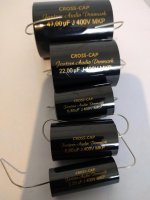
Cliff undertook to replace the crossover capacitors for a friend.I really don't know why anybody would want to attempt an "upgrade" for it...
He specified MKP capacitors (see attachment) as replacements for the old electrolytics, but discovered he could not fit them due to their size and the difficulty of dismantling the internal structure of the speaker.
The original electrolytics in the speakers date from the late 1970s - what's your opinion on their likely present condition, WiseOld?
Attachments
I’ve often found that electrolytic values have increased with age in crossover circuits.
I’ve used polyester/Mylar capacitors in place of electrolytic before and it seemed to work fine when polypropylene had been too bright or messed with the response in other ways.
I’ve used polyester/Mylar capacitors in place of electrolytic before and it seemed to work fine when polypropylene had been too bright or messed with the response in other ways.
Cliff undertook to replace the crossover capacitors for a friend.
He specified MKP capacitors (see attachment) as replacements for the old electrolytics, but discovered he could not fit them due to their size and the difficulty of dismantling the internal structure of the speaker.
The original electrolytics in the speakers date from the late 1970s - what's your opinion on their likely present condition, WiseOld?
If the caps are defective, or measure far off value, sure, they'd need replacing, like anything else.
Otherwise, I'd leave well enough alone.
But people do whatever they want, and I limit my input anymore because people don't listen to me.
I'd rather talk to a wall.
I was about to disagree with this. Then you wrote something else which shows a different side..If you change the type of filters and use different slope ( steeper or softer) and aproach ( make them Linkwitz Riley as example) there will be enough difference with the original as they'll probably sound really different as outcome. Will it be better or not will depend from preference ( and compromise as there is few 'absolute' better in loudspeakers, this is an 'art' of compromise each way you take) so it is difficult to say.
That is why everybody is cautious in theyr answer to you.
You attended to this acoustic configuration issue. It was a problem that had enough degrees of freedom to be able to be fixed electronically.no more 'waistbending' around 800hz in directivity as i lowered woofer/mid to 560hz instead of 800hz
Perhaps the manufacturer had chosen to compromise sound for power handling. It is not clear why such a limiting situation existed.
My point was that a crossover can, when all things are open to change, be made to disappear. It is more science than art... Art is when you take a random speaker and try to fix it at the crossover network alone with no or single measurements and can't see why it won't come good.
^ i agree with you about 'art'. But when you don't get what hapen or how it's done it is easy to think people mastering the knowledge have some kind of magic. And i agree too about science and the possibility to have invisible passive filtering. It still requires skills i don't have.
I repeat i do not master at all loudspeakers passive filters so have great respect for those who have ( and i'm kind of frustrated as was able to fix some big complex analog consoles when i was still working in studio, but this is different field in a way much easier...).
About the waistbending yes once i understood it was an acoustic issue from the use of direct radiators ( 15" up to 750hz to a 3" 3/4 up to 4,5khz) it was an 'easy' fix from the xover freq. The use of 48db/octave FIR on the mid helped to mitigate breakup and allowed to go up to 6khz but the waistbending reapeated up there ( less severe and bothersome to me).
I've been perplex about the choice Technics made on this particular model but it seems it was a design choice of the time ( this is the case2 presented but even T.Gravesen seems to be clueless about it except from a directivity pov):
Design-Criteria
I think this choice is linked to the fact they had developed some 'new' drivers's serie for their flagship of the time ( SB-M1, which used flat aluminium honeycomb membrane, concurent to Sony's Apm range) and used the one they had at hand on their smaller models, with compromise...
There is some irony to this though as people who heard the SB-M1 and the SB-M2 prefered the smaller one. I had not heard the M1 but can say the M2 sound very good given their age and share some quality to Genelec 1037 for example ( even more since they are multi amped and dsp driven, all proportions kept however as they can't have the power ( spl) or the waveguide's benefits Genelec have). I would attribute some of the ressemblance to the acoustic impedance of the 15": in the low mid and bass it is potent to say the least.
I hesitated to post about the mod i did to them here though as i don't want to give false hope to Cliff: the E100 use horns and nothing will be as easy about them without ( extensive) acoustic measurements: eg how do you cross a 12" at 1,2khz ( with theorical 90* directivity) to an horn which have 150* without flaws?
Last edited:
Interesting..
Finding some middle ground with the EQ method, how it can give insight. Would you hear your mentioned acoustic problem that way? Maybe find that you can dial up an excess of 800Hz and yet it still sounds lacking, unsupported. Maybe hear an incoherence based on this discontinuity of the spectrum. You'd learn where the problem is and know it is at that crossover..
I think if it appears anyone is being cautious with their replies, it's a big topic.I hesitated
Finding some middle ground with the EQ method, how it can give insight. Would you hear your mentioned acoustic problem that way? Maybe find that you can dial up an excess of 800Hz and yet it still sounds lacking, unsupported. Maybe hear an incoherence based on this discontinuity of the spectrum. You'd learn where the problem is and know it is at that crossover..
I most certainly do want to listen to you. 😎I limit my input anymore because people don't listen to me.
I was making a serious request for your professional opinion regarding the longevity of the electrolytics in Technics speakers of that era.
The trouble is that Cliff has no means of access to the original electrolytics because of the way the circuit board is enclosed, so he can't measure them.
I too wondered whether he'd be better off just leaving well enough alone.
Galu,
I think if Wiseoldtech statement was pointed toward someone in the thread it would be at me:
Technics SB-5 capacitors
https://www.diyaudio.com/forums/multi-way/351820-technics-sb-5-capacitors-2.html#post6138948
😉
That said i want to be clear: i never thought ( and still do think) Wiseoldtech comments to be not valuable.
It is clear you have a lot of experience and a lot to share about many subject, Technics gear in particular ( i do own ( and have owned) other Technics gear including SL1200 mk2 and SL10 and all the comments you made about them were spot on to me.
In the previous thread my experience have been different that is all. I hope it is clear i'm not trolling you Wiseoldtech.
And there is interesting comments in the linked thread about brass bolts which could be of interest in here.
It is more or less what led me to modify them: i was bothered by the frequency range around 800hz and as i used them to work on and had direct comparison to many other monitors at workplace ( including the Genelec) i knew something was off to me. Tryed eq them it didn't changed the behavior ( once i discovered BSC and how to calcul and eq it it made a big change but still...).
Then thanks to this place i got into modelisation, directivity behavior of individual drivers of different size, then i modeled the box and the location of drivers and then was the answer... and the missing link about radiated power and problems related to reflected sound in room.
I spent a lot of time on them but in the last 5 years many things i known from a theorical pov clicked in place with what i whitnessed in reality with them. But now i think i can't make them 'better' to my liking than what i have as the design choices made impose limits.
Iow i cut my teeth on them and it was very interesting journey opening to many other things including being able to consider a design from scratch.
My next pair will borrow many of their positive points but done differently as i want something much more point source than this classical three way layout.
Sorry to disgress...
Well i hope not to confuse Cliff to much with all this rambling! At least it'll point to things to investigate in future.
I think if Wiseoldtech statement was pointed toward someone in the thread it would be at me:
Technics SB-5 capacitors
https://www.diyaudio.com/forums/multi-way/351820-technics-sb-5-capacitors-2.html#post6138948
😉
That said i want to be clear: i never thought ( and still do think) Wiseoldtech comments to be not valuable.
It is clear you have a lot of experience and a lot to share about many subject, Technics gear in particular ( i do own ( and have owned) other Technics gear including SL1200 mk2 and SL10 and all the comments you made about them were spot on to me.
In the previous thread my experience have been different that is all. I hope it is clear i'm not trolling you Wiseoldtech.
And there is interesting comments in the linked thread about brass bolts which could be of interest in here.
Finding some middle ground with the EQ method, how it can give insight. Would you hear your mentioned acoustic problem that way? Maybe find that you can dial up an excess of 800Hz and yet it still sounds lacking, unsupported. Maybe hear an incoherence based on this discontinuity of the spectrum. You'd learn where the problem is and know it is at that crossover..
It is more or less what led me to modify them: i was bothered by the frequency range around 800hz and as i used them to work on and had direct comparison to many other monitors at workplace ( including the Genelec) i knew something was off to me. Tryed eq them it didn't changed the behavior ( once i discovered BSC and how to calcul and eq it it made a big change but still...).
Then thanks to this place i got into modelisation, directivity behavior of individual drivers of different size, then i modeled the box and the location of drivers and then was the answer... and the missing link about radiated power and problems related to reflected sound in room.
I spent a lot of time on them but in the last 5 years many things i known from a theorical pov clicked in place with what i whitnessed in reality with them. But now i think i can't make them 'better' to my liking than what i have as the design choices made impose limits.
Iow i cut my teeth on them and it was very interesting journey opening to many other things including being able to consider a design from scratch.
My next pair will borrow many of their positive points but done differently as i want something much more point source than this classical three way layout.
Sorry to disgress...
Well i hope not to confuse Cliff to much with all this rambling! At least it'll point to things to investigate in future.
Last edited:
To be quite candid, Cliff, I think you may have bitten off more than you can chew! 😀
With no knowledge of how a linear phase crossover works, and no access to measuring equipment, the most you can do is clone the existing crossover network, employing exactly the same type of components.
Thanks Galu.
And thanks to all the other contributors, not least of all Wiseoldtech.
I'm greatful for all the guidance and advice.
I'm calling it a day.
Given my level of expertise, the unknown engineering Technics employed, and lack of ability to measure before and after, I'd be only fooling myself.
I'm very glad that, with assistance, the Midrange is now functioning.
I can't undervalue that to the sound improvement achieved.
I'll limit my input to freshening up the metal connections, polish the veneer, cut and polish the enamel, and replace the plastic nuts on the binding post with brass to improve the speaker lead connection.
One of the capacitors in Technics crossover was a non electrolytic type (poly??), that, although +-10%, may not have deteriorated as would electrolytic types.
Importantly, I don't want to devalue my friends speakers which are totally original.
One big positive, I've met (online) many great characters and have enjoyed the dialogue.
For now, I'll start small and hopefully build my knowledge base.
This thread has revealed many things I was never aware of previously.
I've got the Dali 606's, the B&W 110's, & the Silcrons to recap.
Thanks guys.
Cliff 🙂
An approach I take with more valuable things to be modified is to develop a separate portion that stands alone, and not mess with the original. This is usually a lot of extra work when extra fitted parts are involved.
Rare old cars often have numbered engines that are matched to a specific car, wouldn’t be wise to grenade those when an old truck engine would be a better candidate.
Rare old cars often have numbered engines that are matched to a specific car, wouldn’t be wise to grenade those when an old truck engine would be a better candidate.
There are those "sometimes" which the DIY'er must say no to, when thinking about an upgrade, particularly on something as complex as that Technics system.
Repairs to bring back the original performance is fine, but again, a line has to be drawn sometimes.
Repairs to bring back the original performance is fine, but again, a line has to be drawn sometimes.
Hi Guys.
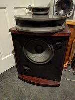
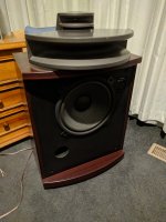
These were the speakers we had pitched in over.
I've reassembled them, polished the veneer, gave the enamel a mild cut with brasso, and was able to get the Midrange speaker functioning.
Tonight I've been playing a selection of well recorded tracks.
Enjoy them very much.
A strong bass, with detailed top end.
I could have got them to sound even better had I been able to lift them off the floor and orientate them correctly.
Attachments
- Home
- Design & Build
- Parts
- Minimum acceptable AWG for Inductors on Crossover build?