Pic to explain #2 better... I worded it very poorly, apologies. No more posting for me. Clearly tired, and I didn't even have a green beer tonight. 
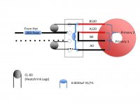
Main fuse in IEC was 800VA / 120 = 7A was closest.
400VA/120 = 3A5 was closest for each transformer.
Obviously doubled up for dual mono.
Again, hopefully someone will chime in to note if that's applicable in your situation, or if I'm way off.

Main fuse in IEC was 800VA / 120 = 7A was closest.
400VA/120 = 3A5 was closest for each transformer.
Obviously doubled up for dual mono.
Again, hopefully someone will chime in to note if that's applicable in your situation, or if I'm way off.

ItsAllInMyHead's diagram looks correct.
Extreme_Boky's diagram, not so much. The AC is shorted. Note that each pair of screw terminals in a connection block is connected together.
Extreme_Boky's diagram, not so much. The AC is shorted. Note that each pair of screw terminals in a connection block is connected together.
neither is correct
I forgot it's the darn 110V and the primaries need to be paralleled... (or only one winding is used?)
also, what type of terminal block are we talking about here? each terminal is isolated from all others??
my drawing would be okay for 230V (sans one CL60)
EDIT:
second try... terminal block has the links (or the DIY-er to provide the links if there aren't any)
Attachments
Last edited:
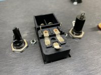
It is wired as shown in post #141 (sans fuse) which also follows the n00b guide as well. There are just two of everything. They are both fed to the center posts of the terminal block where I can common feed from the mains. I like the idea of fuses for each. I’ll make that happen. The nice thing about the terminal blocks is it’s easy to reconnect things.
To answer the terminal block question, each pair of terminals between the barriers are connected beneath.
Appreciate the feedback 🙂
To answer the terminal block question, each pair of terminals between the barriers are connected beneath.
Appreciate the feedback 🙂
Last edited:
separate fuse for each
separate soft start ( whichever sort) for each
Thank you, sir. Will do. 🙂
Do the CL60s provide enough soft start or would you suggest a different solution like that in the DIY store?
Good morning, Chris -
Sorry for the confusion. Below is what I think you have, and to me was/is correct. Quick mock up. Your actual wiring is much neater. 😀

If you want to fuse each transformer, you could possibly have a single hot and neutral mains wire from the IEC to another smaller terminal block. You could fuse it after the block to split it out for each transformer and remove the jumpers from the big block. I ran 2 hot and 2 neutral lines from the IEC and fused the hot. Yank the appropriate fuse to test each independently. I'm sure there's a much more elegant solution than how I did it. Clearly there's a better way to type it out. 😀
Sorry for the confusion. Below is what I think you have, and to me was/is correct. Quick mock up. Your actual wiring is much neater. 😀
If you want to fuse each transformer, you could possibly have a single hot and neutral mains wire from the IEC to another smaller terminal block. You could fuse it after the block to split it out for each transformer and remove the jumpers from the big block. I ran 2 hot and 2 neutral lines from the IEC and fused the hot. Yank the appropriate fuse to test each independently. I'm sure there's a much more elegant solution than how I did it. Clearly there's a better way to type it out. 😀
@Chris in Milwaukee , did you use "thermal paste" on your power supply diodes as well as insulator pads ?
You got it. You’re quite the graphic artist! Thanks for the interpretation. I’m sure it will be very helpful for the next person doing this as well. Site search is how I learned as much as I have to date. 🙂Good morning, Chris -
Sorry for the confusion. Below is what I think you have, and to me was/is correct. Quick mock up. Your actual wiring is much neater. 😀
View attachment 933296
If you want to fuse each transformer, you could possibly have a single hot and neutral mains wire from the IEC to another smaller terminal block. You could fuse it after the block to split it out for each transformer and remove the jumpers from the big block. I ran 2 hot and 2 neutral lines from the IEC and fused the hot. Yank the appropriate fuse to test each independently. I'm sure there's a much more elegant solution than how I did it. Clearly there's a better way to type it out. 😀
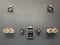
For ease of maintenance, I’ll probably add a couple of these to the back panel. Maybe not the 10-for-$6 variety, but panel-mounted fuse holders nonetheless. I’d love to use ATC fuses or similar, but I don’t know that those are rated for 120V applications.
Attachments

On the diodes, yes. Regarding insulator pads, are you referring to the transformers or output FETs? No thermal compound of any kind near the transformers. I haven’t mounted the amplifier boards yet. But I did purchase the Keratherm insulators for the semis. I presumed those didn’t use any kind of thermal paste.@Chris in Milwaukee , did you use "thermal paste" on your power supply diodes as well as insulator pads ?
Last edited:
I like the back panel idea. That could work well. If you were considering ATC, most likely not. I can't be sure, but those are 32VDC max most often. Not good in this application. There could be an exception outside of my limited scope of knowledge.
If you wanted a "covered" option inside the chassis to reduce risk of little pokey fingers or tools making contact with live wires, I linked an option below. However, $$. There may be other more cost-effective options, but this is one I found. If it's even a consideration, have someone doubly ensure that it's properly rated. I'm reasonably sure but...
BUSSMANN In-Line Fuse Holder, Fits Fuse Type Glass and Ceramic, Fuse UL Class Not Class Rated, 0 to 20 A - 1DD10'|'HFA-R - Grainger
PS - For the graphics. I should have shown the electrical connections between terminals within the block. Sorry, Extreme_Boky / Ben. I appreciate you guys calling that out. Everything should be crystal clear, particularly with mains wiring. Fail. 😱
Installed the separate fuse holders for each individual PSUs. Everything clears nicely. However, it turns out if you manhandle a cheap fuse holder, they’ll self destruct. I grabbed the back with pliers to give it that extra little 1/2° twist to get the tabs just so, and BLAM! Fuse holder parts everywhere. So another order goes out and they’ll be here Tuesday. Maybe should have bought the Bussmans, but I was lured into Amazon Prime delivery. 😛
Attachments
Just couldn't spring for the 10-pack, huh? Kidding... Kidding... 
Another tidbit. Do you use spades and "big audiophile" speaker wire and/or a "big audiophile" power cable? If so, try that orientation with your terminals and a power cord in place to see if that's what you want. Don't want to have to pull out the torque wrench after everything is wired up to loosen them. 😀 May not apply, but just in case.
Another tidbit. Do you use spades and "big audiophile" speaker wire and/or a "big audiophile" power cable? If so, try that orientation with your terminals and a power cord in place to see if that's what you want. Don't want to have to pull out the torque wrench after everything is wired up to loosen them. 😀 May not apply, but just in case.
be happy
same happens even with expensive drek
seen my share of melted (various) Frtch drek, handled by regular Audiphools**
( **that type which removes mains fuse and switches, then install Frtch and whatnot of interconnecting bits and pieces, in enthusiastic soldering orgy)
same happens even with expensive drek
seen my share of melted (various) Frtch drek, handled by regular Audiphools**
( **that type which removes mains fuse and switches, then install Frtch and whatnot of interconnecting bits and pieces, in enthusiastic soldering orgy)
Just couldn't spring for the 10-pack, huh? Kidding... Kidding...
Another tidbit. Do you use spades and "big audiophile" speaker wire and/or a "big audiophile" power cable? If so, try that orientation with your terminals and a power cord in place to see if that's what you want. Don't want to have to pull out the torque wrench after everything is wired up to loosen them. 😀 May not apply, but just in case.
Yeah, shoulda bought the ten pack. 😛
I pondered the orientation. Those connectors only give you four keyed choices, I thought that may be the lesser of the evils. May need to reconsider. I’m using bananas myself, but might want to try another type one day. Which way do you orient yours?
be happy
same happens even with expensive drek
seen my share of melted (various) Frtch drek, handled by regular Audiphools**
( **that type which removes mains fuse and switches, then install Frtch and whatnot of interconnecting bits and pieces, in enthusiastic soldering orgy)
That expression your face makes after you say to yourself, “it’s just a tiny movement, no need to loosen it...”. Then the “special words” come out. 😡
- Home
- Amplifiers
- Pass Labs
- New Aleph J builder from Wisconsin, USA