Been playing with KiCad.
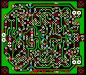
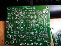
Here is a trial of AX14p in semi surface mount. I know it's not a great layout technically. But maybe you're willing to try something better and post it here too.
Attached are all the files.
Lol and yes I used an electrolytic as the input cap bypassed with a small film capacitor. optionally
Regards
Here is a trial of AX14p in semi surface mount. I know it's not a great layout technically. But maybe you're willing to try something better and post it here too.
Attached are all the files.
Lol and yes I used an electrolytic as the input cap bypassed with a small film capacitor. optionally
Regards
Attachments
Last edited:
I always order my pcbs from jlcpcb and never faced a problem. whats the nature of your problem?
PS
i understand that there is some problem with their online processing software.
attached are more traditional gerbers which should work well.
Hi Prasi
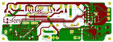
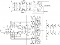
Is there a jumper in the red marked place?
View attachment 934003

I'll let Prasi give more info, but that's not a jumper. There seems to be two options. one for using a transformer with two separate windings each with its own bridge. and then an alternative where you use the other pads for a single bridge rectifier if you have a 15-0-15 centre-tap transformer. In the second case you don't populate the positions for the two bridge rectifiers as in case 1. The pads with the circles around them appear to be for option 2.
attecment did not upload
I must say its for only 1 bridge rectifire,
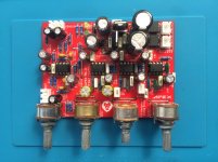
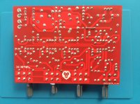
TB3 tone control
Hi
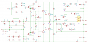
The Apex TB3 Rev3 tone control circuit is ready. It works perfectly. Volume bass medium treble is good. Warning to friends who will do it alone reverse direction on c19 pcb.
Hi
The Apex TB3 Rev3 tone control circuit is ready. It works perfectly. Volume bass medium treble is good. Warning to friends who will do it alone reverse direction on c19 pcb.
Attachments

Hi
The Apex TB3 Rev3 tone control circuit is ready. It works perfectly. Volume bass medium treble is good. Warning to friends who will do it alone reverse direction on c19 pcb.
good job fazil , kindly post the pcb pdf files.
"Warning to friends who will do it alone reverse direction on c19 pcb."
C19 on my My boards look fine..
C19 on my My boards look fine..
Please help me, How to open gerber files
You need a Gerber viewer. gerbv works great for me.
Yes what Vostro says is correct.
when using CT trafo, a single bridge is populated at pads with circle outline and CT is connected to the ground pad with circle outline..
when using CT trafo, a single bridge is populated at pads with circle outline and CT is connected to the ground pad with circle outline..
yes C19 orientation is wrong. it should be reversed. thanks for pointing out. , eagle eyes.
corrected sch and stuffing guide is attached here.
regards
prasi
corrected sch and stuffing guide is attached here.
regards
prasi
Attachments
Last edited:
yes C19 orientation is wrong. it should be reversed. thanks for pointing out. , eagle eyes.
corrected sch and stuffing guide is attached here.
regards
prasi
Thank you. I see now.. please ignore me on post 13554
Hello
I have purchased PCBs for AX14 from PCB Way.
I have skimmed through this thread to find a BOM but couldn't find one. I wonder if some one would please help with following
1- What is the maximum supply voltage?
2- except 0R33 being 5w, is there any other resistor which should be > 0.6w ?
3- D4,5,6,7 should be 1N4004 or 1N4007?
4- is there any recommendation about capacitor types in certain places?
5- I understand to adjust Bias, measure the voltage drop across 0R33 and adjust P1 for 20mv, is this correct?
Thanks in advance
- Home
- Amplifiers
- Solid State
- 100W Ultimate Fidelity Amplifier