Nothing to connect.
They are vias.Is the way to connect traces on the bottom side.
so no jumper?
Last edited:
No - please only put components where the overlay says otherwise your amps will not work!
When you are finished soldering and before testing, can you take a picture of both modules and post them up here and the kx-Amp crew will check them for you.
🙂
When you are finished soldering and before testing, can you take a picture of both modules and post them up here and the kx-Amp crew will check them for you.
🙂
Tony, just put the same ones in both amps.
The standing current is not adjustable and this was a design choice to keep the amp simple. You will have differences in current between amps due to resistor tolerances eg the emitter degen resistors), bias controller transistor gains and Vbe’s.
(If you cannot get more transistors, let me know what you have in your junk box and you can use those for the bias controller)
To cut a very long story short:
Replaced all the 'B' Grade BC transistors in AMP 'A' with the original 'C' grade ones I had removed.
On the 'test bed' (amp mounted on heatsink but the heatsink not 'installed' in the chassis)' the amp had a voltage (between Q8/Q9 Emitters) of 218 mV vs 325 mV originally. Yay!
Installed heatsink in the chassis, powered up and Amp A had a voltage of > 700 mV 😕
Replaced all the BC transistors (other than Q1/Q2) with brand new 'C' grade.
Out of chassis the voltage was 206 mV. Cool. Put back in Chassis: > 700 mV 😕
By trial and error found that disconnecting the RCA input ground to chassis 2nF polystyrene capacitor of Amp A the voltage immediately dropped back to the ± 200mV region 😕
Disconnecting the Amp B RCA cap made no change to the Amp B voltage (174 mV).
More anon ..
I have attached a copy of the amp build which has changed from the original as I've removed the extra cap bank.
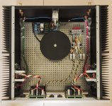
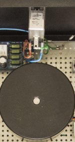
After a lot of trial and error I came up with the PSU as per the picture.
The transformer secondary is connected to a terminal block which feeds a snubber network at the top (2 by 150 nF caps with 2 by 51R resistors in series).
The Transformer secondary output is split and goes to 2 banks of 2 fuses and a central '0V' line to supply the 2 Ripple Eaters on the front chassis panel.
From there the ± 32V from the REs goes to each Amp, 'A' and 'B'.
With the DC voltages floating (not earthed), both amps installed along with the RCA input caps , amps are stable and at 179/187 mV respectively after ± 1 hour.
Problem is there's around 3 Volt 50 Hz ripple on the amp outputs (sine wave)
Back to the first issue:
I had tried earthing the DC line prior to adding the amps themselves.
1. Direct earthing at the transformer secondary '0V' terminal block connection - worst possible choice with the snubber network next to it.
2. Earthing at 'Ripple Eater B' (the amp 'B' ripple eater) 'Ground Lift' - better but not by much. I had chosen just one RE Ground lift to earth because of possible ground loops if both RE ground lifts were used.
3. Because the '0V' lines are joined at the transformer secondary block I only run one '0V AC' to each RE. As the RE is designed to take both common 'central 0V AC' transformer lines directly I was thus only using one RE '0V AC' connector on both REs. So I connected the Ground to the 'spare' 0V AC terminal and got the best performance of all - < 100uV (Averaged 256) both channels (but no amps).
4. Connected both amps 'off chassis' and measured performance < 150uV. 😀
5. Put the amps/heatsinks into chassis, connected RCA wire - then the problems began as described above. 😡
So:
1. With the configuration of earthing RE 'B' '0V' line to earth, Amp A emitter voltages skyrocket unless I disconnect the RCA 2nF cap.
2. Connecting both RE ('A' and 'B') oV lines to earth doesn't help (only Amp 'A' was monitored at this stage)
3. Switched the earth to RE 'A' then Amp 'B' Q8/Q9 emitter voltages skyrocket to > 700 mV. whilst Amp A stays stable.
4. Disconnecting the 2nF RCA cap from Amp B returns the voltage to 'normal' levels.
So the amps are pretty equivalent.
I can't pick up anything on the scope (60 MHz) that would indicate any massive oscillations that would cause this phenomenon. Not sure if they could be beyond that range? The output transistors run very hot, very quickly at > 700mV
Somewhere along the line there is seems to be a problem with trying to earth - either via the ground lift, or direct to ground, - the DC supply lines.
But I'll keep on trying.
1. I know that if I don't use the RCA bypass caps the problem goes away but is this the correct solution or is there a bigger problem I'm missing here?
2. How should one earth the system with 2 ripple eaters in parallel? Both or one? Ground lift or 'direct to ground'?
Two things for certain:
1. Grounding an amp DC is something which is not trivial.
2. Snubbers and DC grounds should be kept as far away from each other as possible (based on a lot more work than I've covered here) for optimal performance.
Sorry for the length of this note but might aid others if they run into similar problems. The problem appears to be with my specific setup though and not the amps themselves.
Lastly, the chassis RCA inputs were shorted with dummy loads and all RCA cable checked for continuity/short circuit. RCA screen is connected at amp side but not at the RCA input. When 'off chassis' testing was done the amp RCA input was shorted with a dummy load comprised of a 1 " cable twisted (joined at the end but obviously no RCA 2nF cap to chassis - hence no signs of problems until installed).
Attachments
“RCA screen is connected at amp side but not at the RCA input.”
Just trying to understand this.
You should have your RCA’s input connectors fully isolated from the chassis. You then run the screen cable from each RCA to its coresponding module. The screen (signal ground) must be connected both ends. If you did not do this and had the 2nF RFI cap in place, you would get problems (nice HF input loop).
Just looked at your pic. The 2nF caps have to be right at the input connectors with very short leads. As they are they will cause problems. Suggest you remove them for now. In any event, if you are not getting any RFI problems for now, leave them out.
Can you make a drawing of what you have? Is you transformer a split secondary or is it two separate secondary windings?
Having 2 ripple eaters complicates it a bit, but we should still be able to get it quiet.
Last edited:
Bonsai
This is a good question, specifically with regards to your drawing in your KX document, page 34.
Thanks,
Anand.
2. How should one earth the system with 2 ripple eaters in parallel? Both or one? Ground lift or 'direct to ground'?
Having 2 ripple eaters complicates it a bit, but we should still be able to get it quiet.
This is a good question, specifically with regards to your drawing in your KX document, page 34.
Thanks,
Anand.
I think I would personally prefer double ground lifters with double ripple eaters.
When it comes to polsol's problem, I have no idea why Iq would vary with grounding.. If it was hum or output DC offset, maybe, but Iq..
Could there be a 'current leak' via the heatsink (transistors not properly isolated)? I'm just thinking it would be more 'violent' if that was the case..
Is this bias voltage measured without load(speaker/resistor) on the output, and measured emitter to emitter?
Have you double checked offset voltage on the output too?
Anand, good point. I’ll do a doc for dual mono and dual RE add add it to the GL presentation - will have to be later this week - I’m in the middle of debugging th3 new HPA-1 headphone amp
“RCA screen is connected at amp side but not at the RCA input.”
Just trying to understand this.
You should have your RCA’s input connectors fully isolated from the chassis. You then run the screen cable from each RCA to its coresponding module. The screen (signal ground) must be connected both ends. If you did not do this and had the 2nF RFI cap in place, you would get problems (nice HF input loop).
Just looked at your pic. The 2nF caps have to be right at the input connectors with very short leads. As they are they will cause problems. Suggest you remove them for now. In any event, if you are not getting any RFI problems for now, leave them out.
Can you make a drawing of what you have? Is you transformer a split secondary or is it two separate secondary windings?
Having 2 ripple eaters complicates it a bit, but we should still be able to get it quiet.
Hi Bonsai,
The RCA cable is 2 core screened. White core is connected to RCA 'live', Blue to signal ground and the screen is connected at the amp J4 but not at the RCA plug - to prevent ground loops (I read that somewhere the screen should be 'single ended' to prevent a ground loop).
Maybe it's the screen that should be connected via 2nF caps to chassis ground and not the signal ground?
Transformer is a Novatel FE500/25: 25-0, 25-0, 500 VA but not internally screened. Maybe the latter is a problem? Purchased ±10 years ago from Farnell but not previously used other than for testing other amps. Might also be sold as 'Multicomp'.
The original RCA 2nF caps were connected next to the RCA sockets - directly to the chassis corner screws, by the polystyrene cap wires, no additional cable - < 1" from the RCA sockets. See photo.
The problem was there even when connected like this - why I decided to run cables directly to the earth ground node under the IEC plug to see if a 'direct' earth connection might work - without success.
With the 2 RCA caps disconnected and the AC '0V' (Transformer connected as 25-0-25) junction on the barrier block connected to earth (Otherwise no earth or ground lift connection).
Last night I ran the amp for around 1/2 hour. The voltage across R14/R15 (measured between Q8/Q9 emitters) was 179mV on one and 181mV on the other vs your specs of 200 ± 50 mV for class AAB.
The high Q14/Q15 voltages only occur when the RCA caps are connected to the chassis.
Photos:
Original short RCA cap connections
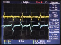
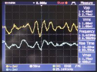
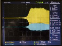
Snapshot of both channels 5 mV 5ms
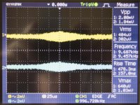
256 average on both channels 2 mV and 1ms
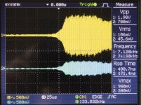
Snapshot of both channels 2mV 50 ns - the only other waveform I could find on my scope.
Monitoring R14/R15 voltage on both channels simultaneously (not fully warmed up - approx at 15 minutes power on).
No RCA input caps, probes at X1, otherwise as mentioned : snubber and secondary AC 0V connected direct to chassis ground node.
BTW, I have run both sine and square waves up to 100 KHz when the boards were connected 'off chassis' and all looks well.
Attachments

I think I would personally prefer double ground lifters with double ripple eaters.
When it comes to polsol's problem, I have no idea why Iq would vary with grounding.. If it was hum or output DC offset, maybe, but Iq..
Could there be a 'current leak' via the heatsink (transistors not properly isolated)? I'm just thinking it would be more 'violent' if that was the case..
Is this bias voltage measured without load(speaker/resistor) on the output, and measured emitter to emitter?
Have you double checked offset voltage on the output too?
Hi Rally,
Thanks for your interest.
Problem with a double ground might be ground loops? Which is why I wasn't keen to try.
Transistors are mounted using mica washers (sliced by myself to make thinner) and heat sink compound. Checked all for short to heatsink before powering up. All 'O/L'.
The EBC leads from the transistors run fairly close to the heatsink where the leads 'bend' but not touching AFAIK. But it's a good point so I'll take the Heatsinks out again at some stage and move the board (and thus tranny leads) a couple of mm more away from the heatsink. The heatsink anodising is a non-conductor, I believe, so it wouldn't show on resistance measuring if they were. But perhaps there's a capacitive effect?
Otherwise the amps run fine, I think, without the RCA caps. Which is why I'm scratching my head.
Offset adjustments made, when warmed for around 1 hour, to ± 10 mV from 0V. No problems encountered (worked as expected)
When I encountered the original problem on the left channel (Amp A) I attached my 8 ohm dummy load and it made no difference - R14/R15 voltage was > 700 mV within seconds - and rising rapidly - so I switched off.
When I replaced the BC's for the 4th time (I also 'matched' the BCs on HFE, as close as possible, as well) on Amp A I also checked R12/R13 with the amp/HS 'off chassis' one was 230mV, the other 240mV so no problem (higher mV was probably due to increased HS temperature because the HS was lying 'flat' on my work bench, not vertical, hence not cooling efficiently.
BTW, when I encounter the high voltages and switch off the power, the transistor case temperatures drop dramatically almost immediately showing the transistors are making good thermal contact with the heatsink.
If your amp is working without the RFI caps then that’s a good start.
You must keep the RFI cap leads short and right at the input connector. The cap must go from the signal ground to the chassis. At RF, this makes the interconnect screen, the source equipment (assuming a metal housing, and you amplifier a single enclosure. Any common mode RFI impinging on the interconnect cable goes to the chassis through the RFI cap, and not into your amplifier.
Re the screen on your cable - ok got it. The most important thing for hum reduction is the the signal and the return are close together (twisted) to keep the loop area small. You are good to go with your set-up.
Just leave your screen as is - no need to connect it to any caps etc.
Your offsets and bias currents are all in good range.
I’ll come back on the other stuff a bit later - got errands etc to run unfortunately.
Yes -16 Ohm is ok but of course the output power will be reduced
Po =( V^2)/R
yes, I know. Thanks
Tony I still owe you some answers - will try a little later today.
Hi Bonsai,
No rush. Tidying things up this weekend, like the temp wiring I've used.
BTW, Compared to PVC encasses wires I find the silicone encased wires twist more easily, is easier to twist, doesn't require cable ties (holds its shape), and of course has a higher temperature resistance. The downside is that this cable type 'nicks' quite easily so one cannot use (tight) cable clamps anyway and needs to be kept away from other objects that might inadvertently damage it.
Had the amp running for over an hour, no load, minus the RCA caps and top an bottom chassis panels. Voltage across R14/R15 stabilised at 185 mV ± 2 mV for both 'A' and 'B' amps 😀
Voltage waveforms as previously.
Distance between heatsink and the bottom of the amp PCBs after I had 'straightened' them so the power and driver transistor legs were parallel to the heatsink surface (they were bent slightly towards the PCB previously (but not touching the heatsink) so the PCB/heatsink distances were smaller):
Left hand side (Amp 'A') ± 5.5 mm
Right hand side (Amp 'B') ± 6.5 mm
Before removing the RCA caps (they were still attached to the chassis but not to the RCA cable ground) I tried connecting them to the RCA cable using small crocodile clips. No difference in R14/R15 voltage on Amp 'B' but Amp 'A' immediately jumped from 185 to 285 mV (previously > 700 mV with the caps connected).
There are no 'standoffs' fitted to the boards. They are held in place by the transistor legs only.
It was a quick final 'what-if' test but just maybe there is a correlation between the distance the amps are mounted from the heatsinks and my problems. Capacitive effect with the Amp PCB tracks?
I have no idea but thought it might be worth a mention.
Cheers
Well I've been doing a far bit of fiddling and tidying up of the wiring harness whilst trying to sort out the issues with one or both channels passing too much current.
Without any RCA caps the amp was running without problem (no load as yet) but trying to resolve the problems I was getting with attaching 2.2nF polystyrene caps to the RCA inputs I did a little more work.
I purchased some 2.2nf ceramic caps and, using 'flying leads (dual crocodile clips - 15 cm per length) attached them between the RCA signal grounds and case earth.
The amps stayed stable at around 185 mV across R14/R15 but I found a waveform with a 25ns timebase as per picture "2Caps, Dual Earth. At least a success from previous when one or both voltages jumped to > 700mV. 🙂
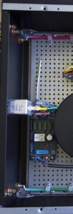
Whilst messing around with changing the earth connections of the 2 caps I noticed that if I moved the rear IEC socket the waveform 'jumped'. This IEC socket is a 'press in' type and although the cutout was done with a die, and the top/bottom tolerances are within 1mm of the IEC socket, it still wobbles around. The Earth output of the IEC socket is connected to the perforated chassis base. (See 'Rear IEC socket pic). It was something I had meant to check and never got round to it. What I found was that I had, in reality, 2 earths (continuity measured with multimeter):
One from the IEC socket metal cover to chassis (resistance varies from 0 ohms to Open Loop - and in between - when 'wobbled' around)
The main 'Earth ground' from the IEC socket to the perforated base.
Thus, I assume, causing some form of earth loop.
First step, detach the 'main earth' from the perforated base (ground via IEC case to chassis/case): Pic "Both Caps, Case Earth".
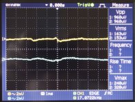
So I put some electrical tape around the IEC case to isolate if from the main chassis and used the scope to see what happened: Pic "Main Earth, 2 Caps".
The caps were placed between signal ground and chassis using the 'flying leads'.
Then, with the same earthing, I tried connecting the RCA caps between the
RCA signal ground and the main earth node: Pic "MaIn Earth, Caps to Main Earth node". An improvement.
Lastly a scope picture of the amp minus any RCA caps: "Main Earth, No Caps". The best of all.
Somewhere along the line there seems to be a problem with the overall earth scheme. Initially the chassis/case was earthed via the IEC socket case whilst the perforated base was earthed directly to the IEC plug. The perforated base is connected onto the chassis/case by 3 separate metal standoffs on both sides. Perhaps isolating the perforated base from the chassis/case with nylon standoffs and only having one earth connection between the two might have been a better idea?
Anyway, these notes are just in case someone else has a similar problem with a similar construction of separate base from chassis and might help them.
Without any RCA caps the amp was running without problem (no load as yet) but trying to resolve the problems I was getting with attaching 2.2nF polystyrene caps to the RCA inputs I did a little more work.
I purchased some 2.2nf ceramic caps and, using 'flying leads (dual crocodile clips - 15 cm per length) attached them between the RCA signal grounds and case earth.
The amps stayed stable at around 185 mV across R14/R15 but I found a waveform with a 25ns timebase as per picture "2Caps, Dual Earth. At least a success from previous when one or both voltages jumped to > 700mV. 🙂
Whilst messing around with changing the earth connections of the 2 caps I noticed that if I moved the rear IEC socket the waveform 'jumped'. This IEC socket is a 'press in' type and although the cutout was done with a die, and the top/bottom tolerances are within 1mm of the IEC socket, it still wobbles around. The Earth output of the IEC socket is connected to the perforated chassis base. (See 'Rear IEC socket pic). It was something I had meant to check and never got round to it. What I found was that I had, in reality, 2 earths (continuity measured with multimeter):
One from the IEC socket metal cover to chassis (resistance varies from 0 ohms to Open Loop - and in between - when 'wobbled' around)
The main 'Earth ground' from the IEC socket to the perforated base.
Thus, I assume, causing some form of earth loop.
First step, detach the 'main earth' from the perforated base (ground via IEC case to chassis/case): Pic "Both Caps, Case Earth".
So I put some electrical tape around the IEC case to isolate if from the main chassis and used the scope to see what happened: Pic "Main Earth, 2 Caps".
The caps were placed between signal ground and chassis using the 'flying leads'.
Then, with the same earthing, I tried connecting the RCA caps between the
RCA signal ground and the main earth node: Pic "MaIn Earth, Caps to Main Earth node". An improvement.
Lastly a scope picture of the amp minus any RCA caps: "Main Earth, No Caps". The best of all.
Somewhere along the line there seems to be a problem with the overall earth scheme. Initially the chassis/case was earthed via the IEC socket case whilst the perforated base was earthed directly to the IEC plug. The perforated base is connected onto the chassis/case by 3 separate metal standoffs on both sides. Perhaps isolating the perforated base from the chassis/case with nylon standoffs and only having one earth connection between the two might have been a better idea?
Anyway, these notes are just in case someone else has a similar problem with a similar construction of separate base from chassis and might help them.
Attachments


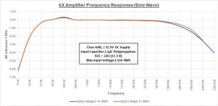
I did some frequency response checks on the two amplifiers this morning for interest sake.
No load values as per attached (Excel) image for anyone who is interested.
Measured overload/clipping at 1.15V RMS @ 1KHz.
Used the frequency generator at 1.15V RMS output and reached 300 kHz before the 5A fuses blew. The modified Ripple eaters (had changed the series output transistors to the more robust 2SA1295/2SC3264) were barely warm.
Ran again at 1V RMS input and reached 400 kHz before reducing the voltage back down to 500 mV RMS. Running short on 5A fuses ...
Attachments
- Home
- Amplifiers
- Solid State
- Hifisonix kx-Amplifier