Self healing is not the reason why cheap capacitors lose value ... they are poorly made , thats all
And made in china by a western company does not equal to some local "entrepreneurs" copying that stuff in a shitty factory across the road .
And made in china by a western company does not equal to some local "entrepreneurs" copying that stuff in a shitty factory across the road .
Last edited:
show us the figures....
I spoke to my colleague - the capacitors tested were on the AC power line and measured less than half the nominal capacitance. They removed them and dissected one - that is my data point for one failure mechanism for X2 self-healing caps.
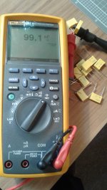
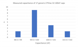
The attached images show testing of generic yellow-cased X2 caps using a Fluke 289 (factory calibrated). The histogram shows the measured capacitance of a handful (17 as it happens) spilled from the bag of 50 and tested.
The comparative testing charts show one of those generic X2s against an EPCOS and a TRW of comparable voltage rating.
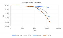
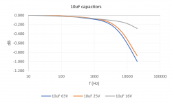
The other charts show the frequency response of 16V polar electros with increasing capacitance. And one chart of 10uF electros with increasing voltage rating.
Attachments

we are talking polypropylene caps, yes? electros are notorious for tolerance...from the charts, i do not see significant changes....
t's your money to waste...
Frankly I think it's ridiculous not to use Chinese parts.
I agree with you. In your amplifiers there is not a single genuine quality part.
I agree with you. In your amplifiers there is not a single genuine quality part.
the greatest challenge to any diy'er is to make an amp that sounded like a million dollar amp using one dollar parts....
@N101N Every part in ANY amp I design and build is genuine. A lot of them even comply with AEC-Q200. I don't use fake/counterfeit crap, buddy. Whether or not it's up to your exacting standards is another story. I'd love it if you could actually hear one though instead of assuming you know everything. You might be surprised you like the sound of an unconventional tube amp.
we are talking polypropylene caps, yes? electros are notorious for tolerance...from the charts, i do not see significant changes....
The photo shows X2 metallised polypropylene caps under test, and the the first chart shows the results of testing 17 of those X2 caps. All were very close to the nominal capacitance - I recall that I stopped testing, willing to accept the small risk that one of the remaining 33 capacitors in the bag would deviate from the nominal value by more than 2%.🙂
The second chart shows the comparative comparative capacitance across the bandwidth 1Hz to 20kHz of three polypropylene capacitors of similar voltage rating and physical size. Note that the Y-axis of the chart shows capacitance relative to the capacitance at 1kHz of the device under test. I adopted this metric to evaluate how well each capacitor maintained its value across the test bandwidth - I was not evaluating how close each capacitor was to its nominal value.
In the chart, the X2 cap is the yellow trace - it shows the most constant capacitance across the bandwidth and is an excellent candidate for use in precision small-signal filters. The other two capacitors will also do a very good job, perhaps not so precise as the X2.
The third chart shows the same test applied to 16V electrolytic capacitors of various capacitances. This time the Y-axis of the chart shows capacitance relative to the capacitance at 10Hz of the device under test (rather than 1kHz) to evaluate how well each capacitor maintained its value across the test bandwidth irrespective of its nominal value.
The capacitance rolls off with frequency, more so for larger capacitors - larger both in nominal value and in physical volume. I found this to be the case for all polarised electrolytic capacitors that I tested. The roll-off was faster and greater than for most film capacitors, including larger film capacitors. You ask about the effect of the large tolerance of values of electrolytic capacitors - feel free to print off the chart and adjust it for the tolerance bandwidth of electroltytic capacitors and report your analysis. You may also want to consider and state the implications of the roll-off for power-supply filtering at higher frequencies and how this might this affect the filtering of higher frequency rectification products? What approach would you recommend to address any issues?
The fourth chart shows the same test applied to 10uF electrolytic capacitors with increasing voltage ratings. Again, feel free to print off the chart and adjust the curves to reflect the likely tolerance of capacitor value, and any potential effect on power supply input filtering (a common application of electrolytic capacitors of lower value), and let us know how you might address any issues that you see.
And I would welcome others showing their test results so that all of us can benefit and learn.
have you tried doing tv scanning tubes?
I'm not sure who this was directed at, but I use sweep tubes almost exclusivively.
... I found this to be the case for all polarised electrolytic capacitors that I tested.
Did you test with a DC voltage applied to the capacitor? Apparently they work better that way?
We're sweep tubes meant to be used for audio as triodes? Does it matter?
The triode curves of a *AV5 match those of a 2A3 - so what?
The 6DJ8 was designed for cascode VHF duty but people use them for audio all the time. again - So what?
What point are you trying to make dude?
The triode curves of a *AV5 match those of a 2A3 - so what?
The 6DJ8 was designed for cascode VHF duty but people use them for audio all the time. again - So what?
What point are you trying to make dude?
Were sweep tubes made for linear service?
The answer is yes, otherwise the picture on your old CRT screen would be distorted.
The tube may not have been linear the horizontal sweep had to be.
- Home
- Amplifiers
- Tubes / Valves
- Anyone familiar with these caps?