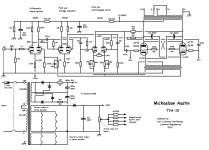
I have a Michaelson and Austin TVA-10 which uses a 36V winding on the transformer for all of the driver tubes' heaters.
The complement is 2 x ECC83 (differential phase splitter), 2 x ECC83 (push pull voltage amplifier) and 2 x ECC81 (push pull bootstrapped driver).
The tubes are heated in 2 strings of 3 tubes.
The issue is that the driver tubes, one in each string in particular, light up like lightbulbs for a couple of seconds when the amp is switched on.
This issue has been discussed on other threads, and the general response is 'do not worry about it', but I will need to replace those tubes soon, and I'd like to ensure the longevity of the replacements.
If one looks at the Philips tube data sheet for the ECC83, it contains the following statement ...
"In case of series supply a current-limiting device must be inserted in the heater circuit for limiting the current when switching on".
I'll look at the specs of inrush current limiters to see if I can match the steady state current (450mA in each string), but this will sap some of the heater supply, which is already a bit lower than spec (36V as opposed to 12.6 x 3 = 37.8V).
Another option would be to rectify the 36V, but that could put some extra burden on the transformer.
Is there a standard current limiting solution in these cases?
Attachments
The issue is something even CarlsonsLab has made a current limiter for and something I'm interested in too (although parallel connected).
Tech Tips Tuesday Dirty Little Secrets - YouTube
Probably the easiest route provide a simple bypass resistor or NTC. Then wait a couple of seconds and switch out. That way the chain of filaments warm up and start developing resistance then the resistor current limit is bypassed.
Tech Tips Tuesday Dirty Little Secrets - YouTube
Probably the easiest route provide a simple bypass resistor or NTC. Then wait a couple of seconds and switch out. That way the chain of filaments warm up and start developing resistance then the resistor current limit is bypassed.
Last edited:
The power transformer AC heater voltage (regardless of series or parallel connections) depends of -mostly- the mains voltage (fluctuation), and the heater coil properties (calculated current, DCR).
The series connected filaments resultant resistance is the sum of individual filament's resistance (plus wiring), so the given voltage depends of the heater coil DCR and the series filaments resistance.
Aging of tubes the filament wire is becomes thinner, so the resistance will be growing a bit, the current draw is decreasing, so the voltage on heater coil would be growing a bit.
The deteriorating (series) filament get is the same power, but the healthy (series) filaments not.
If any tube in series chain ruined, all of the stopping. If any of the shorted, all of them would be ruined (too much current).
Therefore I'm not a fan of series connected filaments.
The rectified and current stabilized heater structure helps a little.
I thing a series resitor shorted by a time-delayd relay is a solution.I have a Michaelson and Austin TVA-10 which uses a 36V winding on the transformer for all of the driver tubes' heaters.
The complement is 2 x ECC83 (differential phase splitter), 2 x ECC83 (push pull voltage amplifier) and 2 x ECC81 (push pull bootstrapped driver).
The tubes are heated in 2 strings of 3 tubes.
The issue is that the driver tubes, one in each string in particular, light up like lightbulbs for a couple of seconds when the amp is switched on.
This issue has been discussed on other threads, and the general response is 'do not worry about it', but I will need to replace those tubes soon, and I'd like to ensure the longevity of the replacements.
If one looks at the Philips tube data sheet for the ECC83, it contains the following statement ...
"In case of series supply a current-limiting device must be inserted in the heater circuit for limiting the current when switching on".
I'll look at the specs of inrush current limiters to see if I can match the steady state current (450mA in each string), but this will sap some of the heater supply, which is already a bit lower than spec (36V as opposed to 12.6 x 3 = 37.8V).
Another option would be to rectify the 36V, but that could put some extra burden on the transformer.
Is there a standard current limiting solution in these cases?
Note that each string will consume 150mA ( not 450mA ) , the relay will have to short 300mA . The resistor will be active during your delay period, app 5s
33 ohm 2w could be a good starting point.
This amp is how old? Ever needed to replace a tube because of a heater failure in this amp? I guess not. Sure a NTC or even a small value resistor can help if the voltage is too high.
How to Use NTC Thermistors for Inrush Current Limiting – Passive Components Blog
How to Use NTC Thermistors for Inrush Current Limiting – Passive Components Blog
This was "normal practice" in many types of tube radios I worked on but what I noticed was it did not seem to occur so much in Mullard tubes .
I am talking about genuine -original Mullard tubes of the era but did occur in some other makes .
While this might be a "big issue " here it wasn't in communication circles.
OTOH some say its Mullard tubes that do that but personally I didn't notice this , what did worry me at the time was ones that "looked " dim which I though was due to low emission but was just down to manufacturing design.
Just so this doesn't become a big issue the Mullard UK factory tested its tubes for long life etc ( as it had a good reputation --then ) and I saw the banks of tests with multiple old school gauges just like a massive tube tester and it was "designed in " to live with the switch on surge.
Of course this being 2021 life is different including scam/low quality tubes badged as a tube company of good standing even down to the printing on the tubes .
Try an experiment.
Find a 6 volt transformer and a couple of croc clip leads, take out the EECxx valves and power each filament in turn pins 9 to 4 and then 9 to 5. Make sure the valves are cold for an hour or so before trying them.
Chances are one or more of the filaments will 'light bulb'... Some brands do it more than others.
Have you confirmed that all heaters share the voltage to within say +/-5% when heated up? Have you measured the voltage across the driver heaters to see if they hog voltage on power up? All heaters are going to pass the same high initial current, so it will be an unequal surge voltage that causes stress. You could parallel some back-to-back zeners cross the driver heaters to force better equalised voltage (and hope the zeners survive) during power up.
You could also try and find some vintage barretters and rejig the heaters, but then the heater winding would have to supply 150% of existing continuous current.
You could use only valves from the same manufacturer and era.
You could also try and find some vintage barretters and rejig the heaters, but then the heater winding would have to supply 150% of existing continuous current.
You could use only valves from the same manufacturer and era.
Last edited:
are you having humming issues? if not, then that flashing on turn-on is a mere annoyance...
and if that really annoyed you, then change it to one that does not flash on turn-on...
i wonder what AV8 would say if here were here today...
and if that really annoyed you, then change it to one that does not flash on turn-on...
i wonder what AV8 would say if here were here today...
Last edited:
ECC83 = 12AX7. ECC81 = 12AT7. Buy OS 12AX7As and OS 12AT7As. That "A" suffix indicates controlled heater warmup time and was needed in the days of series heater string TV receivers.
All ECC8[1-3] are designed for series heaters as they were used in television sets together with P** tubes ( 300mA filament)ECC83 = 12AX7. ECC81 = 12AT7. Buy OS 12AX7As and OS 12AT7As. That "A" suffix indicates controlled heater warmup time and was needed in the days of series heater string TV receivers.
are you having humming issues? if not, then that flashing on turn-on is a mere annoyance...
and if that really annoyed you, then change it to one that does not flash on turn-on...
i wonder what AV8 would say if here were here today...
Hi Tony, and the others that offered advice.
I'm sure AV8 would not think too highly of this issue, but there was advice given in the original tube data sheet regarding current limiting, and I wanted to explore options.
Yes, I do have a humming issue that develops after the amp has been playing for some minutes, and I'm assuming the driver tubes have only had 40-something years service, so are ready to be pensioned off. I will test them all, but I am discovering that tube testing is not an exact science, and curves and emission levels do not tell the whole story for driver tubes.
Looking at the NTC Thermistor data sheets, since my voltage supply is a bit tight, it looks like a single CL-140 (1.1 amps max steady state ) for the supply to all 6 tubes (max current 900mA) should be the best option, with perhaps a CL-210 being a better option since it is specced for 1.5 amps max steady state, so would be less stressed.
I am also in the camp that 'if it was designed that way then leave it', but I think the M&A TVA-10 was designed down to a price point, and an NTC device is a trivial change.
Thanks again!
Richard
Your tubes are connected in 2 lanes, each with heaters configured as 12V. Ok ?
Then each land with draw 150mA , 2 lanes in parallell gives 300Ma current.
Not 900mA.
Then each land with draw 150mA , 2 lanes in parallell gives 300Ma current.
Not 900mA.
Your tubes are connected in 2 lanes, each with heaters configured as 12V. Ok ?
Then each land with draw 150mA , 2 lanes in parallell gives 300Ma current.
Not 900mA.
36v, 2 strings, each string with 3 tubes in series, each tube consuming 150mA. So 450mA per string.
36v, 2 strings, each string with 3 tubes in series, each tube consuming 150mA. So 450mA per string.
Err, NO. Current does not increase for series connected circuits.
Each string consumes 150mA, so 300mA for both.
Try this way round, each ECCxx uses 1.8 watts (that is 12v x 0.15A)
So 3 x ECCxx use 5.4 watts. If you divide 5.4 by 36 (the voltage through 3 in series) you end up with 0.150mA.
Remember, current stays the same for series circuits and voltage increases. For parallel circuits the voltage stays the same and current increases.
Alan
Last edited:
Stupid me! Yes, I'm sorry, that is correct.
Then it makes it a bit awkward finding an NTC to fit.
Then it makes it a bit awkward finding an NTC to fit.
If the heaters do not draw identical current, then the voltage will not divide up evenly among the tubes in the series string. Series string little ol' radios used tubes designed to have controlled warmup characteristics and close tolerance current ratings so that they warm up together and share the voltage as required. I would not series 12AX7's & such, since they were designed for use in paralleled, not series heater settings. They might work, or they might not. That's not reliable design.
Again, the ECC81 82 & 83 are designed for series string, have been from their first delivery.If the heaters do not draw identical current, then the voltage will not divide up evenly among the tubes in the series string. Series string little ol' radios used tubes designed to have controlled warmup characteristics and close tolerance current ratings so that they warm up together and share the voltage as required. I would not series 12AX7's & such, since they were designed for use in paralleled, not series heater settings. They might work, or they might not. That's not reliable design.
- Home
- Amplifiers
- Tubes / Valves
- Series heated tubes