The hassle with using an NTC is that it has to stay hot for the working continuous current level, which is a current level down to circa 30% of NTC max current rating. That means for 300mA continuous, the max continuous current rating of the NTC should not be above 1A (otherwise the resistance of the NTC may not stay at a low level unless you include some custom thermal insulation). Also the hot resistance of the NTC drops some voltage, so the resultant reduced 'heater voltage' needs to be assessed if it is still ok.
Last edited:
i have a TVA-10 on my bench and there is no tube flash.....i would say go the easiest way, replace the tubes and be done with it...
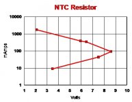
NTC Plot Example
Measured data using a constant current generator in 4 terminal mode.
Applied I Measured E Calculated R
9.23 mA 3.48 Volts 377 Ohms
34.7 7.52 217
91.8 8.61 94
345 6.44 18.7
390 5.95 15.26
1.73 Amps 3.65 2.11
This NTC was made for the TV Buz. Connects between the power
plug & the power source. Made by Nutronics in Sarasota, FL.
About 40 years old. Because of thermal inertia the measurement
settling times are long, up to 10 minutes.
Attachments
Last edited:
Again, the ECC81 82 & 83 are designed for series string, have been from their first delivery.
This is what it says in the Philips data sheet for ECC81, and what prompted my query in the first place.
Attachments
If you are concerned a series resistor and a timed relay could be used. TheThis is what it says in the Philips data sheet for ECC81, and what prompted my query in the first place.
relay shorts out the resistor after a few seconds. A more complicated but better solution is to rectify the AC, add an DC stab circuit configured for a current limiter of 350 - 500mA.
In your case it might be unnecessary as the transformer used has some series resistance. The tubes you have seem to have been working for several 10's of years, chances are that new tubes will last equally long.
That said, if you have hum problems, new tubes might fix that.
Ok, then I think the consensus is to replace the tubes, since they have had a good innings, and take it from there. If the issue persists, then I'll consider the resistor and timer option.
Thanks all!
Thanks all!
This is backed up by old Mullard industrial manuals.
Designed for audio the ECC83 has a long list of operating conditions under both grid bias and cathode bias for voltages-resistor values under different plate voltages and cathode bias resistors and distortion levels .
At lower levels of plate voltage it is recommended to use grid bias .
In reference to post #20.
Last edited:
Ok, then I think the consensus is to replace the tubes, since they have had a good innings, and take it from there. If the issue persists, then I'll consider the resistor and timer option.
Wait, so the consensus is to replace perfectly good working valves, made by Philips in the golden age of valves, for modern lesser copies, because the heaters flare bright on start-up?
FWIW, hum is almost never related to problems within a valve. It's (almost) always the much more obvious issues of old electrolytic caps. Could be, but that's not the hill you want to die on.
YOS,
Chris
What about tying TVS diodes across the heaters to limit the voltage on start?
https://www.mouser.ca/ProductDetail/Littelfuse/15KE15CA?qs=HR2RnyOI4E7PsXLB42TO2A==
https://www.mouser.ca/ProductDetail/Littelfuse/15KE15CA?qs=HR2RnyOI4E7PsXLB42TO2A==
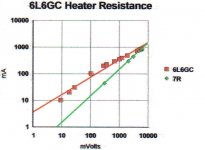
This thread reminds of the Ancient Greek Philosophers, much talk & little action to prove their thoughts are valid. So here are two data sets actually measured several years ago. The cold resistance of a 6L6GC is about one ninth the operating resistance. Other tubes about the same but the thermal time constants are different.
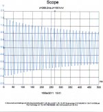
The other plot is the surge across 0.1R on supply of amp with 2x6L6GC, 12AU7, 6AU6 & GZ34. The heater currents are limited by the PS transformer, in the case a Hammond.
The other plot is the surge across 0.1R on supply of amp with 2x6L6GC, 12AU7, 6AU6 & GZ34. The heater currents are limited by the PS transformer, in the case a Hammond.
Attachments
What about tying TVS diodes across the heaters to limit the voltage on start?
1.5KE15CA Littelfuse | Mouser Canada
I have done something like that, when I wanted to string all the heaters in series and one of them grabbed more of the voltage than the others at start-up. I actually just used a pair of series-connected back-to-back Zener diodes to do the job. The only thing is, though, that the required voltage for the TVS diode is about 9V for a tube with a 6.3V heater (i.e. 6.3 times sqrt2), since that is the peak voltage across the heater in ideal circumstances. (Assuming AC heater supply.)
So that means one might actually get something looking almost like a 9V square wave, meaning close to 9V rms, at start-up. Still it could be better than what would happen without the TVS diode, but it can still mean quite a sizable rms overvoltage. In my case it was a 6SN7 in series with some 6082 tubes, and I used the Zener trick to limit the voltage to the 6SN7 heater. Even so, for the peak vs rms reason, the 6SN7 did light up quite brightly at start-up. I never had a heater failure, though.
Trouble is if one heater get a little hotter than the rest from cold its resistance goes up and it takes more of the watts. So it gets hotter and so on. The same thing could happen to old fashioned Christmas tree lights. You can get this to happen by plugging a slightly warmed up 12ax7 with 2 cold ones. Zeners back to back can help a bit but make sure the total voltage is a somewhat more than the max heater voltage * root 2.
HaHa - love the way they go short when blown until you have the last man standing. Remember now you had to have a safety one in there.
The light is more warm (as in tube amps with transformers) as each light is getting a bit lower voltage. Therefore no spare is required.
Sorry, i can not take this topic very serious...
If you really want to solve it then use a current source !
Sorry, i can not take this topic very serious...
If you really want to solve it then use a current source !
As this is still carrying on here is a "potted history " .
In the 20,s like in later era,s radio receivers were manufactured cheaply for the general public by designing tube/valve radios without a mains/power/isolating transformer for those without deep pockets --radios were dear in those days --all down to profit .
An intermediate stage of evolution ( financially ) was an auto transformer with tappings .
In the beginning was the Barretter --I have one 1920,s Edison Screw Barretter with a brown stoneware socket -- they were large .
After that came the Old School Thermistors large resistor style .
Usually one fitted but sometimes two were fitted for paralleling for dial lamps .
Some makes didn't even bother with that and put the output tube/valve first in line from the mains .
All of those tubes/valves used a higher heater voltage than the standard US 6.3 Volts taken from the old automobile battery standard of 6 volts .
Highest was usually 117 volts --again American derived ,voltage was "totted up " to the incoming mains voltage value ---OR American imports used a "Line Cord " for those small and now very expensive Bakelite/plastic colored radios .
Of course not knowing the public cut the cords not realizing the built in resistance , blowing the tubes .
Very large ceramic resistors were also used but they ruined those small Bakelite radios by overheating the casing .
Of course Mullard etc made sure their more modern tubes of serried 12 Volts didn't need those "current stabilizers " by designing it in .
I have of course omitted the later smaller components that came in later days.
In the 20,s like in later era,s radio receivers were manufactured cheaply for the general public by designing tube/valve radios without a mains/power/isolating transformer for those without deep pockets --radios were dear in those days --all down to profit .
Until the very late 20's there were no mains operated radios. Everybody had to do with battery operated radios until the indirectly heated cathode was perfected. The early mains operated tubes on this side of the pond ran on 0.3A. There was quite a large assortment to choose from as many companies jumped in. In many large cities the Edison DC power system was a problem for radio tubes of the time. Without some kind of DC/DC convertor 115V had to do. The rotary convertor was a way to go, both LV & HV wound on the same rotor, spinning in a common field. Surprising to many, the voltages in the rotor are AC, rectification is accomplished by the commutator & brushes on each end of the shaft. In WW2 these rotary convertors were used extensively in mobile apps. I had one for a while, input was 6/12V to 500V @ 160 mA. So could run PP 807s, no problem. Or the Class C 807 in your own personal tank.
The 48 was designed specifically to run where the power was the Edison DC system. Later PP 48s were used in many radios that could run on the 28/32 volt systems on many rural farms. And some different 26V tubes for use in aircraft.
All depended on the IH cathode. My grandmother had a small radio with the resistance wire power cord. Much of the insulation in the cord was asbestos fiber. Asbestos was also used in a flat piece of insulation installed under the chassis of many radios. And the top layer of all the work benches where I did research were covered with transite, a hard fire proof material of Asbestos.
Hard to believe, I'm still here to tell you.😀

And of course you know Ted Rogers developed the indirectly heated cathode from the earlier McCullough tubes.
The radio station CFRB which is now owned by Bell was "Canada's First Rogers Batteryless" 🙂
He died young, too. Edward Samuel Rogers Sr. -- Member of CAB Hall of Fame
The Hammond Museum of Radio. The Rogers Collection
The radio station CFRB which is now owned by Bell was "Canada's First Rogers Batteryless" 🙂
He died young, too. Edward Samuel Rogers Sr. -- Member of CAB Hall of Fame
The Hammond Museum of Radio. The Rogers Collection
Last edited:
- Home
- Amplifiers
- Tubes / Valves
- Series heated tubes