The capacitor is too small for this.
AllenB,
we want to target the high frequency area where the problems lie.

N101N: Do you feel the same way about the tube regulated supply in Loesch’s Legacy?
regulators are also amplifiers, so in effect you have two in one....
i would much rather keep it single amplifier, but that is only me....
Have you seen the circuit diagram of an industry standard voltage regulator? You may get a minor shock.
regulators are also amplifiers, so in effect you have two in one.... i would much rather keep it single amplifier, but that is only me....
Are you talking about how you split up the parts of the amplifier and what chassis you put them on? That's a whole other subject, and one that merits discussion. A complete 300b amplifier can be very heavy, and as you get older you don't want to be lifting any large weights. Evan more since it's awkward putting heavy objects on racks and manipulating them in restricted spaces. And for those of us with smaller workrooms there may not be a big space on the bench.
Some like monobloks. That pretty much solves it - the weight is divided in two. You do have extra PSU components, though.
A common solution is a separate PSU. So all the signal parts go on the signal chassis. You then need to solve the question of high voltage connectors. If you use larger filament supplies for DHTs, especially with chokes, then they can be outboard as well.
Have you seen the circuit diagram of an industry standard voltage regulator? You may get a minor shock.
Getting shocked by just looking at voltage regulator! Wow! 😉 Could explain what you mean, please?
Last edited:
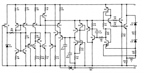
Its actually prettymuch the same for every three terminal regulator. NPN darlington ouptut pair, couple of current mirrors and a bandpass reference. Really nothing special.
LDO's particulairly fixed output ones sometimes use a PNP ouput device and sink the base current for the output transistor through the GND pin.
Linear regulators get a bad reputation for no reason, quality manufacturers make very low noise linear regulators. Yes there is a few uV-PP bandgap noise on the output but that is pink noise.
7805 can be 10uV PP self noise for example, which is nearly nothing. TL431 shunt reference can be 50uV to 5uVpp for the better grade Ti part.
The problem that people get, is they dont filter the supply feeding into the regulator very well. so a normal regulator may have 40db suppression or less at 1Khz harmonic.
You can make your own LM317 high voltage variant with a LM385-1.2 op amp FET and some extra components.
LM723 is insanely quiet if you use it right because of the temperature compensated zener reference. 10uV or so from the datasheet.
Attached LM317 internal circuitry.
Attachments
Last edited:
Have you seen the circuit diagram of an industry standard voltage regulator? You may get a minor shock.
regardless of complexity, any linear regulator will have a series pass element, a reference, and error AMPLIFIER.......so regulators are amplifiers too....
Are you talking about how you split up the parts of the amplifier and what chassis you put them on? That's a whole other subject, and one that merits discussion. A complete 300b amplifier can be very heavy, and as you get older you don't want to be lifting any large weights. Evan more since it's awkward putting heavy objects on racks and manipulating them in restricted spaces. And for those of us with smaller workrooms there may not be a big space on the bench.
Some like monobloks. That pretty much solves it - the weight is divided in two. You do have extra PSU components, though.
A common solution is a separate PSU. So all the signal parts go on the signal chassis. You then need to solve the question of high voltage connectors. If you use larger filament supplies for DHTs, especially with chokes, then they can be outboard as well.
no....
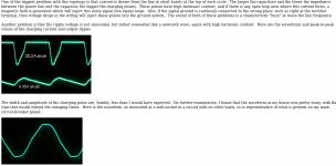
These are twofold, the pass transistor has quite a bit of parasitic capacitance, and the error amplifier gain drops off over frequency.
In the present context, the "shunting to ground" operating mode of the voltage regulators is far inferior to that of the choke. The functional accuracy in the limited frequency band is more or less irrelevant from a distortion point of view. There is a saying that the voltage regulator is the poor man`s choke.
Upon an investigation of paramagnetic and ferromagnetic polarizability, things become anything but simple or straightforward. Polarizability is a quality of merit. A related parameter is conductivity. Conductivity is a measure of the ability to carry an electric current. Another term for electric current is mass. Conductivity is also a measure of ionic strength. The main weakness of the vacuum tube is its poor current handling ability.
The modulation occurs as a natural reaction to excitation, no mediation is required. The amplifier is an attenuator.
Andy,
Given that all of your designs are single ended, haven't you just been mostly listening to the difference in your power supplies recharging and discharging all along?
kind regards
Marek
"listening to the difference in your power supplies recharging and discharging"
What about the constant current loaded preamp? 😛
Motto: one worm climbed out the can. 😛pp
Upon an investigation of paramagnetic and ferromagnetic polarizability, things become anything but simple or straightforward. Polarizability is a quality of merit. A related parameter is conductivity. Conductivity is a measure of the ability to carry an electric current. Another term for electric current is mass. Conductivity is also a measure of ionic strength. The main weakness of the vacuum tube is its poor current handling ability.
1. power supply (after all, an amplifier modulates the power supply into AF so there you are);
The modulation occurs as a natural reaction to excitation, no mediation is required. The amplifier is an attenuator.
Im sorry but that made absolutely no sense whatsoever. It sounds intelligent, but it makes no conclusions, provides little concrete evidence and is rather poorly worded.
You make five different statements that are in and off itself quite true, but you fail to contextualize these. Or even provide insight into your train of thought.
In your last part you say that the amplifier is an attenuator, this is technically true, but try to use the phrase Power supply rejection ratio instead. And given that we are talking 300B SE here, the power supply will have very poor rejection.
A choke supply will suffer from the same problems a linear regulator has: capacitive coupling. A choke supply will do fine over the audio spectrum but HF junk will just zip through.
Each of those concisely formulated statements could be expanded into a chapter. They refer to previous, even more concisely formulated statements. An amplifier that blocks ripple components also blocks signal components. It is the task of the power supply filter to do that. Chokes can cover high frequency bands.
I beg to disagree with your previous assertion that LC filters will attenuate high frequency. Its a logical fallacy to compare linear regulators and passive LC power supply filters, as both will pass HF noise without any meaningful attenuation. Due to parasitic capacitive coupling.
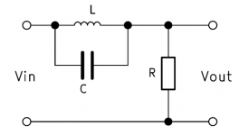
This effect is amplified by the use of paper in oil motor run capacitors, whose self inductance means that they will increase the amount of high frequency impedance roll of dramatically, due to high equivalent series inductance.
If you use old paper in oil capacitors that are quite large, they have a rather high ESL and therefore no meaningful filtering characteristics beyond 10Khz or so.
Only the dreaded industrial parts are optimized for low ESL, ESL was of little concern back in the day.
See attached image, I have chosen to represent the impedance of the power supply capacitor as a resistance that increases with frequency.
Attachments
Last edited:
- Home
- Amplifiers
- Tubes / Valves
- 300b with single stage driver, C3M or?