Me thinks, most importand is the quality in the feedback path because everything on the way to the output will be corrected but the smallest error in the feedback path be stamped onto the output signal.
And frontend transistors and parts should be tightly matched.
Is the BFY81 dual npn usable here ?
HF? transistor with not so high hfe.
And frontend transistors and parts should be tightly matched.
Is the BFY81 dual npn usable here ?
HF? transistor with not so high hfe.
Thanks
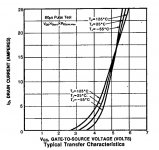
In the Hitachi datasheet the graph only goes to 1A.
From your test, do I understand that right... linearity with 2A bias would be much better than with 0.5A ???
And in the datasheet of IRF250 it looks like you need 6A bias to enter the most linear region ?
Attachments
Last edited:
Hitachi 2SK1058 any good ?
They’re terrible. If you have any, I’ll be happy to take them to “dispose” of them.
...but the IRF looks worse than the Hitachi ?
So for a low power amp with 1.5A bias, a single fet would be better than 3 parallel, with 0.5A each ?
So for a low power amp with 1.5A bias, a single fet would be better than 3 parallel, with 0.5A each ?
Last edited:
So for a complimentary A/B amp each device travels more into the linear region with higher output, while in a single ended A amp the fet travels in the less linear direction on the negative halfwave ???
3x parallel at 0,5A will give you a higher transconductance than 1x at 1.5A.
Try it for yourself in LT Spice.
The models are quite accurate.
https://www.cordellaudio.com/book/Cordell-Models.txt
Patrick
Try it for yourself in LT Spice.
The models are quite accurate.
https://www.cordellaudio.com/book/Cordell-Models.txt
Patrick
Ok, how is that important ?
I never cared of it.
I use Microcap, it includes the SK135 model.
So you think shared current across fets is better ?
I want total 1.5A
I never cared of it.
I use Microcap, it includes the SK135 model.
So you think shared current across fets is better ?
I want total 1.5A
Last edited:
More often than not, the dissipation will decide for you.
I normally design for 25W ~ 30W dissipation per FET.
Patrick
I normally design for 25W ~ 30W dissipation per FET.
Patrick
No.
No real interest in NOS devices when they are still available freshly made.
The TO3P package has no disadvantage.
If anything they have less parasitic capacitance to the heatsink.
The thermal resistance is dominated by the epoxy layer below the die.
Patrick
No real interest in NOS devices when they are still available freshly made.
The TO3P package has no disadvantage.
If anything they have less parasitic capacitance to the heatsink.
The thermal resistance is dominated by the epoxy layer below the die.
Patrick
Ok, how is that important ?
I never cared of it.
I use Microcap, it includes the SK135 model.
So you think shared current across fets is better ?
I want total 1.5A
I like microcap too. It is now free (version 12).
It's a pain to convert some other models, Cordell models for example, to a format recognized by MC12. I had trouble recently (funny, I remember it being easy, maybe I forgot something, or maybe they changed it in MC12).
Bernhard, I was looking at the latmos model included in MC12 and it is not very good. Connect it as a self-biased jfet ccs to see what I mean. Current should not flow AFAIK. Also, it gives unrealistic low distortion spectra in a circlotron config. Or is the circlotron really that good?
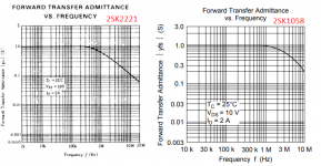
BTW, does anybody have experience with the 2SK2221? Less expensive than 2SK1058. I saw the tests that EUVL posted that indicate the Exicons are the best laterals, and they have the capacitance curves on the datasheet (will be very linear in a complementary output stage, especially for low amplitude signals and zero crossing). How does the K2221 compare to the Exicons?
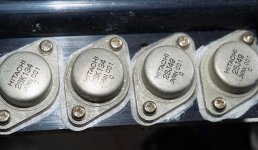
I mount the FET on copper, so heat dissipation is a bit more effective.
Do you know what that C stamp means ?
Thats the transconductance grouping code when the devices are tested for matching purposes.
I should have said "have the edge in transconductance" rather than "are the best".I saw the tests that EUVL posted that indicate the Exicons are the best laterals
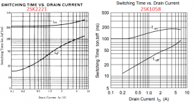
The Exicons seem to be very good in other aspects as well, such as the capacitance curves. I have not found complete capacitance curves in the Hitachi datasheets. The one thing that can be said about the 2SK2221, looking at the datasheet, is that it's slower.
About capacitances and switching times: I used to link one thing to the other, this is wrong of course. Parts can be very fast yet have high and non-linear capacitances. For example: the big sony and yamaha VFETs.
Bernhard, I was looking at the latmos model included in MC12 and it is not very good. Connect it as a self-biased jfet ccs to see what I mean. Current should not flow AFAIK. Also, it gives unrealistic low distortion spectra in a circlotron config. Or is the circlotron really that good?
BTW, does anybody have experience with the 2SK2221? Less expensive than 2SK1058. I saw the tests that EUVL posted that indicate the Exicons are the best laterals, and they have the capacitance curves on the datasheet (will be very linear in a complementary output stage, especially for low amplitude signals and zero crossing). How does the K2221 compare to the Exicons?
When I first simulated a 2SK135 amp in MC6/MC9, the real world results were not far off.
How low is this unrealistic distortion ?
Circlotron has especially low distortion for low amplitude signals and has no zero crossing.
Thats the transconductance grouping code when the devices are tested for matching purposes.
Thanks,
so not matched for Vgs ?
Usually FETs are matched for Vgs ?
I first built a amplifier with single fets, now want test groups of 3.
No matching, just use triples with same date code, removed from PA amps.
What kind of matching would you suggest ?
I was thinking about matching for Vgs at working Vds and working idle current.
And comparing /monitoring the in-amp waveforms across the source resistors.
Last edited:
- Home
- Amplifiers
- Solid State
- Lateral MOSFETs