Kimmosto,
Please consider offering hourly tutoring on your software. Via skype or other communication software.
No nonsense questions, discussions, but exact following of your instructions, you get paid, the customer gets it done and everybody's happy. I do not see any point of wasting time on online yapping, plus the inefficient learning curve for someone who has a project and has specific needs.
That is the efficient way. I can start. Let us know what you think of that. I have a umik but who cares, I'll put it in the shelf and get the proper setup to get the job done.
This is not really tutoring rather than consulting, then think about how many hours Kimmosto would have to invest in this (he may have a day job), then you have to consider different time zones around the world, the language barriers and the ability for people to pay for what is essentially engineering time.
Think about having a day job then coming home to spend your down time updating commercial quality software for free and on top of this having to consult with end users of varying technical knowledge and skill all over the world at all odds hours of the day or night. I would doubt any other commercial entity involved in software simulation for speaker design would offer this type of service as it would be assumed the end user would have at least some type of engineering background.
The forum is the most efficient way of disseminating knowledge and information for VituixCad.
Please consider loudspeaker design as an engineering exercise.
most artists do needs their audience, some artists needs them more then others. but some artists do arts just for them self and give a damn if anyone is watching or listening or not
(he may have a day job)
He really has a day job, dog, wife and house to maintain but no financial problems so it might be quite difficult to get online tutoring/consulting 🙂
what should the procedure be for the bass driver?
Excellent questions.
Some simplified theory: Due to very low position of woofer, shape of woofer's frequency response is maintained to about 1 kHz without floor dip at normal listening distances. There will be quite normal baffle step at far field due to horizontal baffle loss, but sensitivity of radiator is probably 4-5 dB higher than in free field because of floor reflection.
There are couple of possibilities to measure and process the data. This one is probably the simplest, but I don't design that kind of concepts due to experiences from some diy designs few decades ago so I can't say is it the best and most accurate for sure.
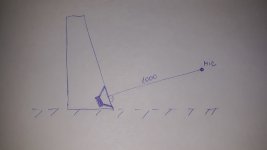
Far field: Keep mic at elevation where axial response (hor 0, ver 0) of woofer is captured while measuring hor 0 deg response. If woofer is tilted up, mic will be a bit higher from the floor than center point of woofer. This captures possible cone break-up which should be included in measurement data to enable compensation with XO.
Measure 0-180 deg in horizontal plane only. You can measure also positive verticals +10...+170 deg if mic is possible to rotate over the speaker so that distance stays constant.
Near field: Standard method.
Diffraction simulation: Create baffle effect response so that virtual mic is at normal listening elevation e.g. Y=900 mm, and axis distance is 3000-5000 mm. Add virtual floor reflection below the speaker. Leave some gap to spikes if speaker has spikes. Attenuate virtual floor reflection by 2-3 dB. Export baffle effect response for Merger tool.
Merger: Standard method is okay because both far field measurements and simulated baffle effect response include floor gain.
Balancing with XO simulation: Axial response should be flat from mid bass to mid-range (without tilting up) because response data includes floor reflection. So anechoic response (without floor) in real life would have 4-5 dB lower SPL at low...mid-bass than simulation shows. This means that also power response in the simulation shows some tilt down from mid-bass to lower mid-range. (There should be clear tilt/step at crossover range if simulation has anechoic data for woofer).
Member
Joined 2003
Far field: Keep mic at elevation where axial response (hor 0, ver 0) of woofer is captured while measuring hor 0 deg response. If woofer is tilted up, mic will be a bit higher from the floor than center point of woofer. This captures possible cone break-up which should be included in measurement data to enable compensation with XO.
.
Mic position like this on the sketch? And no gating, to floor bounce be included?
Attachments
(he may have a day job)
In the same boat, plus 3 kids. So I KNOW how time is precious. That is why everyone who is serious, should put their money where the mouth is and support the product (software) and the artist. Not by chatting here and there, distracting the artist (kimmosto) wasting his time, expecting free help, but paying for his effort and following precise directions to save time, one on one, at a mutually agreed time.
On the contrary, hanging out here and typing questions/answers/suggestions is the least efficient way to getting a project done with the application of VituixCAD. I would imagine, Kimmosto wants to see VituixCAD being used as he designed it to, to create awesome results. And the right way to do that without any extra noise is how I describe above.
Seeing your product being used exactly how you envisioned it, to make further the development of groundbreaking stuff -- that is rewarding, and that makes it worth the effort.
Not explaining things over and over in a forum, to ignorant people, without even knowing if they have any serious intent to use what you have already provided.
Last edited:
Introductory Instructions for North American users new to VituixCAD.
1) Uninstall Microsoft Excel
2) Throw out your USB mic
3) Purchase an XLR Microphone, External Sound card/microphone preamp for dual channel measurements
4) Build any sort of turntable manual or automatic with a stand that puts the speaker in the middle of the room vertically (~1m)
5) Buy Arta
6) Read "Preparation of response measurements for crossover simulation with VituixCAD"
7) Read the instructions again.
🙂
You cannot use VituixCAD properly until you do those 7 steps.
North American traditions are so entrenched that we will have to be dragged kicking and screaming into the light that is proper measurement.
(P.S., it took me over 2 years to complete those 7 steps, I just couldn't wrap my head around the "new" way of doing things, it took me reading German forums to come around)
Mic position like this on the sketch? And no gating, to floor bounce be included?
Yes.
Also this setup has floor dip which could prevent measuring cone break-up accurately. For example if center point of woofer is 130 mm and mic 300 mm above the floor, dip will be at ca. 2.2 kHz.
If dip ruins measurement goals, you can tilt speaker with "something" below rear spikes so that front baffle is vertical. Mic at woofer's elevation moves floor dip to higher frequency. Mic on the floor would be pure ground plane which is probably the best for measuring cone break-up though vertical angle is not exactly 0 deg. Anyway, tilting of speaker is not the easier method but might be needed.
Gating is needed for wall and ceiling reflections also with ground plane measurement. 6-10 ms depending on how far the nearest side wall is.
P.S., it took me over 2 years to complete those 7 steps, I just couldn't wrap my head around the "new" way of doing things
HTG members probably remember this project: My first project is a 4 way speaker...
Few e-mails was needed to explain how to locate mic, connect cables, setup ARTA and rotate speaker/mic while off-axis sequence.
Joaquim aka cochinada made first trials with data processing, but I finished the job and designed the first proper crossover version e.g. with smoother power response. Measurement preparations pdf was originally just an example what I did with ARTA, Diffraction and Merger tools for his 4-way tower project.
All this wasn't too difficult at least for Portuguese 🙂 I would say that process should be much easier today because documentation is quite old, exact and directly usable for typical speaker concepts.
Reliability and resolution of quasi anechoic measurement data and requirement to process near field measurements with simulation cause errors so some inaccuracies/uncertainties remain compared to HC professionals.
recommendation?
>> 3) Purchase an XLR Microphone, External Sound card/microphone preamp for dual channel measurements
Is there a proven mic/sound card combo that does the job well and is reasonable priced? Consistency of equipment would be helpful at this stage...
>> 3) Purchase an XLR Microphone, External Sound card/microphone preamp for dual channel measurements
Is there a proven mic/sound card combo that does the job well and is reasonable priced? Consistency of equipment would be helpful at this stage...
>> 3) Purchase an XLR Microphone, External Sound card/microphone preamp for dual channel measurements
Is there a proven mic/sound card combo that does the job well and is reasonable priced? Consistency of equipment would be helpful at this stage...
Any decent calibrated XLR microphone that comes with a calibration file from a known company.
For interface I am using a Focusrite Scarlett Solo.
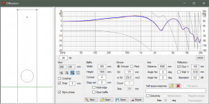
One trick how to create baffle effect response for speaker with single woofer very close to floor. Simulated baffle is about 2x higher than actual. If floor Y=0, woofer Y=150, mic Y=950 mm. Axis distance=5000 mm. Purpose is just to prevent baffle loss below the woofer because simulator does not automatically remove or invert diffraction of the bottom edge on the floor. Sunken edges are kinda mirror sources of diffraction.
Orange trace is normal with baffle loss below woofer. Difference is not radical.
Orange trace is normal with baffle loss below woofer. Difference is not radical.
Attachments
DIY will always go further and do more than commercial, and requires harder design work. When commercial plays it safe, customers will be happy even those that have not been trained in setting up.
I disagree. Commercial goes further in marketing and cost / profit optimisation. The tools available are likely far better in a commercial operation. They use them to optimise margin.
Fair enough. It was worded to suit an earlier part of the conversation (maybe not well enough).
What I have seen is that those that have gone further than any, in terms of cabinet acoustic complexity, room integration, and things like full spectrum all passive acoustic directivity control, have been a small number of DIYers.
Not to mention what is possible when you have the room in question available for integration from the start.
Never mind profit margins, you can't put a price on the considerable amount of labour, or the time spent learning.. but you can build a better speaker for less money in parts alone.
^That sounds correct. Problem was "DIY will always go further", and so would be "Commercial will always go further". Few designers/companies are able to go further than most of the others in both groups. Knowledge, experience, resources, budget, management and time limit/guide both groups.
Any comments about this? VituixCAD Not Summing Same as XSim or PCD7
Comparing programs is not needed to check is calculation accurate or not, and to test/study how different parameters such as delay, location coordinates, scaling etc. work. Comparing is probably the worst and slowest method, and assumed reference app is not necessarily more fact. Functions and accuracy should be studied/tested with perfectly known connections e.g. simple LP/HP/all-pass filter, single resistor/inductor, ideal driver etc.
Comparing programs is not needed to check is calculation accurate or not, and to test/study how different parameters such as delay, location coordinates, scaling etc. work. Comparing is probably the worst and slowest method, and assumed reference app is not necessarily more fact. Functions and accuracy should be studied/tested with perfectly known connections e.g. simple LP/HP/all-pass filter, single resistor/inductor, ideal driver etc.
Introductory Instructions for North American users new to VituixCAD.
1) Uninstall Microsoft Excel
2) Throw out your USB mic
3) Purchase an XLR Microphone, External Sound card/microphone preamp for dual channel measurements
4) Build any sort of turntable manual or automatic with a stand that puts the speaker in the middle of the room vertically (~1m)
5) Buy Arta
6) Read "Preparation of response measurements for crossover simulation with VituixCAD"
7) Read the instructions again.
🙂
The first 3 - can I ask why ? 🙂 Already bought USB mic...
You cannot use VituixCAD properly until you do those 7 steps.
North American traditions are so entrenched that we will have to be dragged kicking and screaming into the light that is proper measurement.
(P.S., it took me over 2 years to complete those 7 steps, I just couldn't wrap my head around the "new" way of doing things, it took me reading German forums to come around)
- Home
- Design & Build
- Software Tools
- VituixCAD