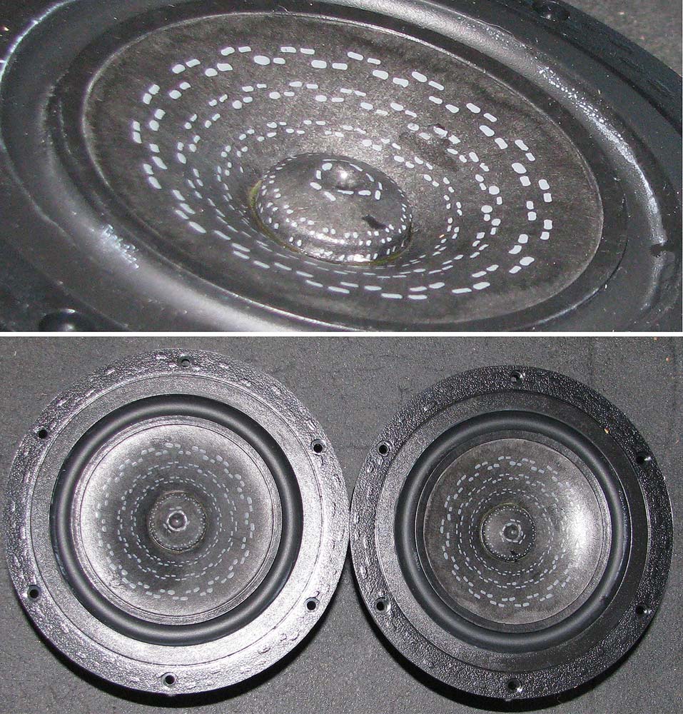
They get some, but not a lot of direct sun. Season and window shade position dependent. Maybe an hour a few days a week for one of them. Pretty much none for the other, and yet they have faded at a similar rate.
Weird.
Still sound good, and I kinda like the look, too. 😀
Hopefully it won't lead to structural issues.
Dave: were yours black from the factory? I figured the color was part of your treatment.
Weird.
Still sound good, and I kinda like the look, too. 😀
Hopefully it won't lead to structural issues.
Dave: were yours black from the factory? I figured the color was part of your treatment.
No, no.
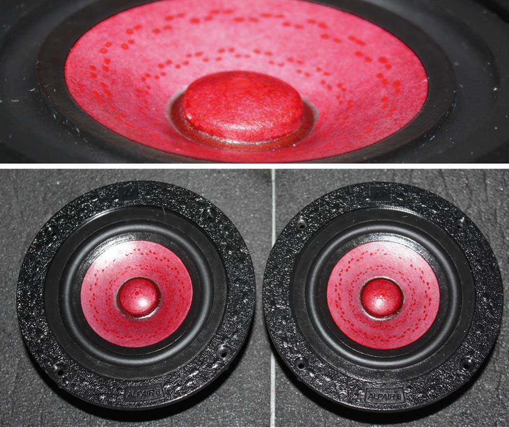
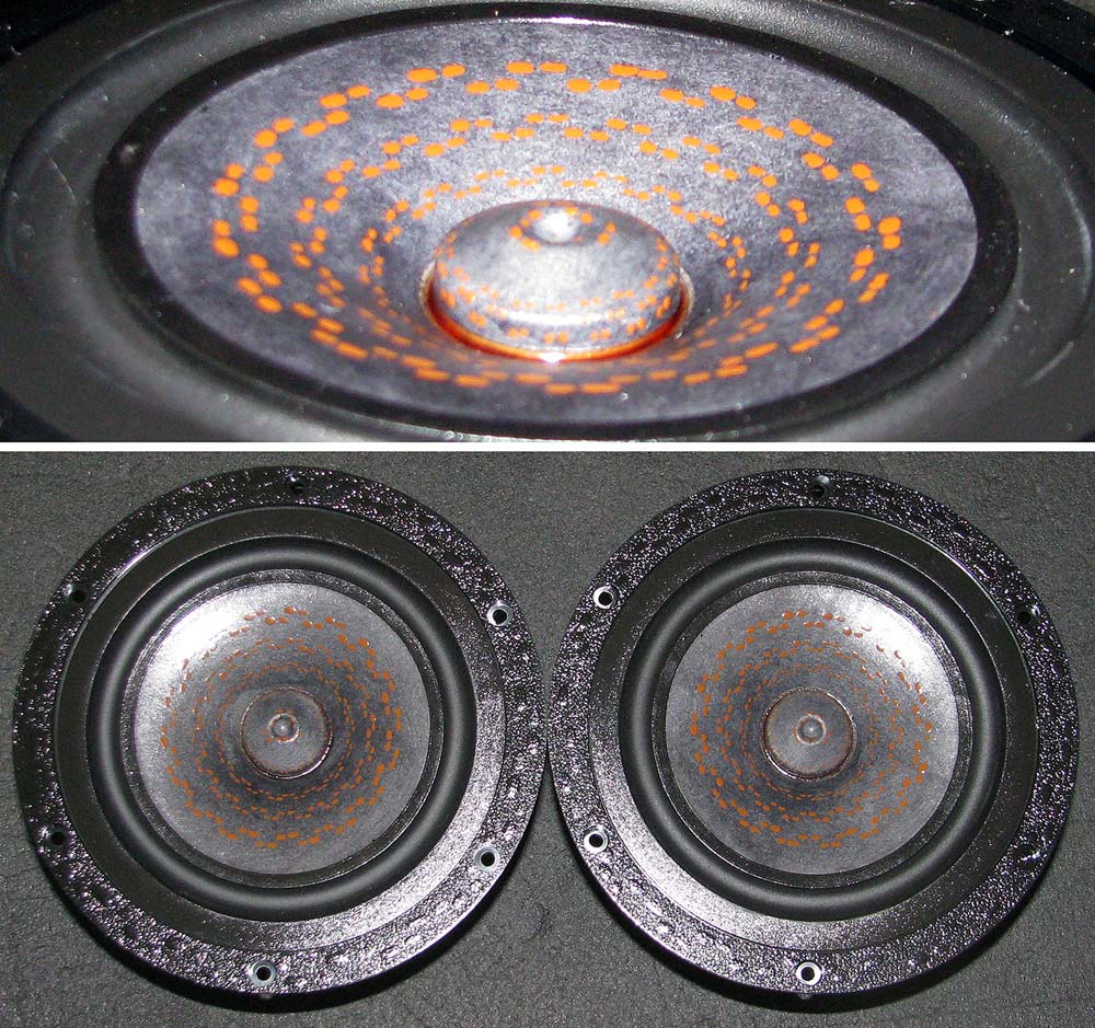
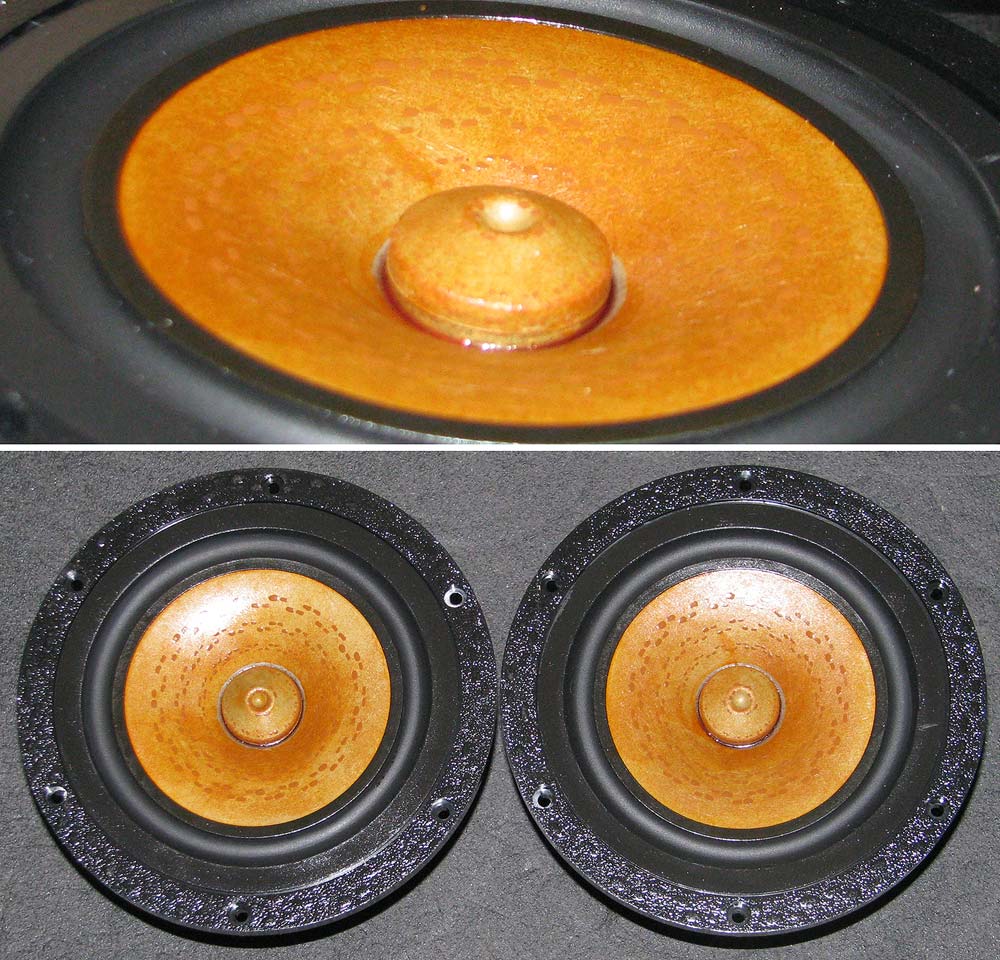
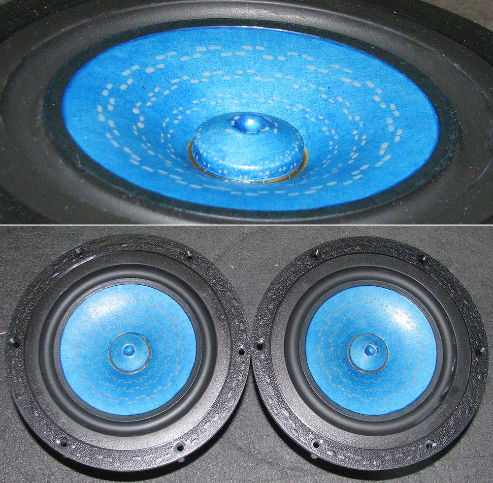
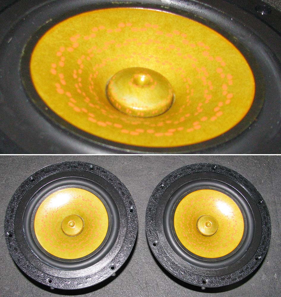
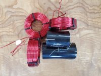
The blue paper cones yield interesting colours when treated with the initial coat of thinned modPodge that is standard procedure on almost all paper cones.
dave
please excuse all the pictures… no green, purple, yellow...
The blue paper cones yield interesting colours when treated with the initial coat of thinned modPodge that is standard procedure on almost all paper cones.
dave
please excuse all the pictures… no green, purple, yellow...
Ah. Makes more sense to me now.
In other news: my crossover parts arrived! I hope to build them this weekend. Is the layout in your picture what I should shoot for, even if I squeeze it into a smaller footprint? The capacitors are HUGE and I want to fit the circuits into as small a space as I can within reason.
In other news: my crossover parts arrived! I hope to build them this weekend. Is the layout in your picture what I should shoot for, even if I squeeze it into a smaller footprint? The capacitors are HUGE and I want to fit the circuits into as small a space as I can within reason.
Attachments
Just keep the inductors as isolated from each other as space permits, and orient them at 90dg to each other and I think you should be fine. But the XO gurus can advise on the finer points.
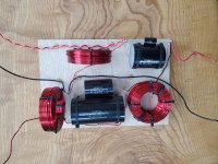
Following your advice and general layout, along with the inductor rules I've seen on Troels site and elsewhere, I plan to go with something like this.
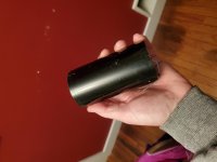
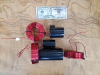
I hope to fit this in an as-yet unconstructed box that I'll affix to the back of the speaker. I dont have much floor space to spare, and these parts are huge! $50 bill is for scale (both physical and financial).
I hope to fit this in an as-yet unconstructed box that I'll affix to the back of the speaker. I dont have much floor space to spare, and these parts are huge! $50 bill is for scale (both physical and financial).
Attachments
I usually try to follow this as a guide. There is a summary image at the bottom of the page.
Placement of coils in crossover networks
Great looking speakers!
Placement of coils in crossover networks
Great looking speakers!
Thanks, GLF.
Yep. That is the page from Troel's site I was referencing. I THINK I'm following his guidance. He certainly manages to squeeze a lot of components into small spaces, and I'm hoping to do the same.
Yep. That is the page from Troel's site I was referencing. I THINK I'm following his guidance. He certainly manages to squeeze a lot of components into small spaces, and I'm hoping to do the same.
I'm very interested in how this turns out. I recently built some 12Ps for my computer in the suggested small reflex vented enclosure and absolutely love the sound and detail. I'm interested in a new project for my living room and these just might be the ticket!
(wish I could get away with just stacking (8) 12ps on top of each other without convergence issues)
(wish I could get away with just stacking (8) 12ps on top of each other without convergence issues)
I built my (huge) crossovers this weekend. After a few false starts due to my ignorance (turns out the red coating on inductor wire is an insulator. Who knew?! 😱 ) they are hooked up and playing.
Compared to my old setup, the upper and middle frequencies are clearer and more forward. This may be the amp, as the 7.3 have historically been driven by my 2a3-based SET and are now driven by a Crown XLS1500. It might also be related to the amount of dampening I used in the big TL. I might have used too much, but compensated for it by turning up the amp that drove the 12pw.
Each big TL has 1040 grams of stuffing, which fills it from top to bottom when moderately teased out.
The midTLs each have 42 grams, starting a couple of inches behind the magnet and increasing in density toward the rear opening.
Much to explore and test in coming weeks.
Attachments
Try the 2A3.
dave
My thoughts exactly...
Upper and mids definitely smoothed out a bit, but bass is still light. This is consistent with initial impressions when running with the PLLXO, where I had to boost the bass to even the sound out. They went lower, but needed more juice to do it.
I suspect that means my TL is over damped. Not sure from where I should remove it. Top? Bottom? Everywhere and just try to tease it out more?
Maybe my midTL is under-damped, letting reflections bounce back through? I suspect I'll only know with testing via REW.
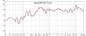
OK. Test 1 results are attached. Amplifier is Bottlehead Stereomour 2a3 SET, pushing a blistering 3.5 watts of raging fury.
Low end is attenuated. Is the solution to remove dampening?
Some ripples up high. If I understand the concept of an aperiodic TL, I think it means I need to add dampening.
A lot of the ripples are likely room effects, as the mic is sitting on top of my couch. 🙂
If someone could please confirm I sure would appreciate it. Kinda out of my depth here, but trying to learn.
Thanks.
Attachments
Last edited:
Bas sis clearly some 10dB down. Ripple between 100 & 200 is likely the room, too close together to be the TL.
This ML-TL is not aperiodic, only the midTL.
The polyfluff needs to be extremely well teased. Pull it all put, put a movie on, give th wwife half ands see how big a pile you can make. Then put half back in, it can be concentrated in the top ywo-thirds if you would like to try that.
dave
This ML-TL is not aperiodic, only the midTL.
The polyfluff needs to be extremely well teased. Pull it all put, put a movie on, give th wwife half ands see how big a pile you can make. Then put half back in, it can be concentrated in the top ywo-thirds if you would like to try that.
dave
Bas sis clearly some 10dB down. Ripple between 100 & 200 is likely the room, too close together to be the TL.
This ML-TL is not aperiodic, only the midTL.
The polyfluff needs to be extremely well teased. Pull it all put, put a movie on, give th wwife half ands see how big a pile you can make. Then put half back in, it can be concentrated in the top ywo-thirds if you would like to try that.
dave
Thanks, Dave.
Understood about the midTL being aperiodic and ML-TL not. That is why I thought to fix some of the rippling up high by increasing the dampening of the midTL only. Figured maybe it wasn't absorbing all of the back energy.
I'll focus on the ML-TL and get busy with the teasing for now. Once I get the bass dialed in I'll work on the midTL.
Best way to fine tune the midTL is by measuring its impedance.
dave
Riiiight. I remember you mentioning that somewhere along the way.
Should that be measured through the crossover, or connected directly to the driver leads? If through the crossover, should I leave the 12pw connected, or take those out of the circuit?
Sorry to be so needy, but I am well out of my depth.
No, driver direct, you are simply looking to flatten the resonance peaks as close to flat as possible.
In the line, with no stuffing, there will be a doouble hump at the bottom.
dave
In the line, with no stuffing, there will be a doouble hump at the bottom.
dave
Quattrofish,
Do you have a DATS device? It would be interesting to see the impedance curves of the drivers:
1. Only with the Alpair 12PW woofers connected (measure w/o the XO)
2. Only the Alpair 7.3 connected (measure w/o the XO)
3. Crossover connected to all the drivers (measure with XO)
Do you have a DATS device? It would be interesting to see the impedance curves of the drivers:
1. Only with the Alpair 12PW woofers connected (measure w/o the XO)
2. Only the Alpair 7.3 connected (measure w/o the XO)
3. Crossover connected to all the drivers (measure with XO)
Real world impedance measures would be nice.
This is the simulated impedance based on real world measures.
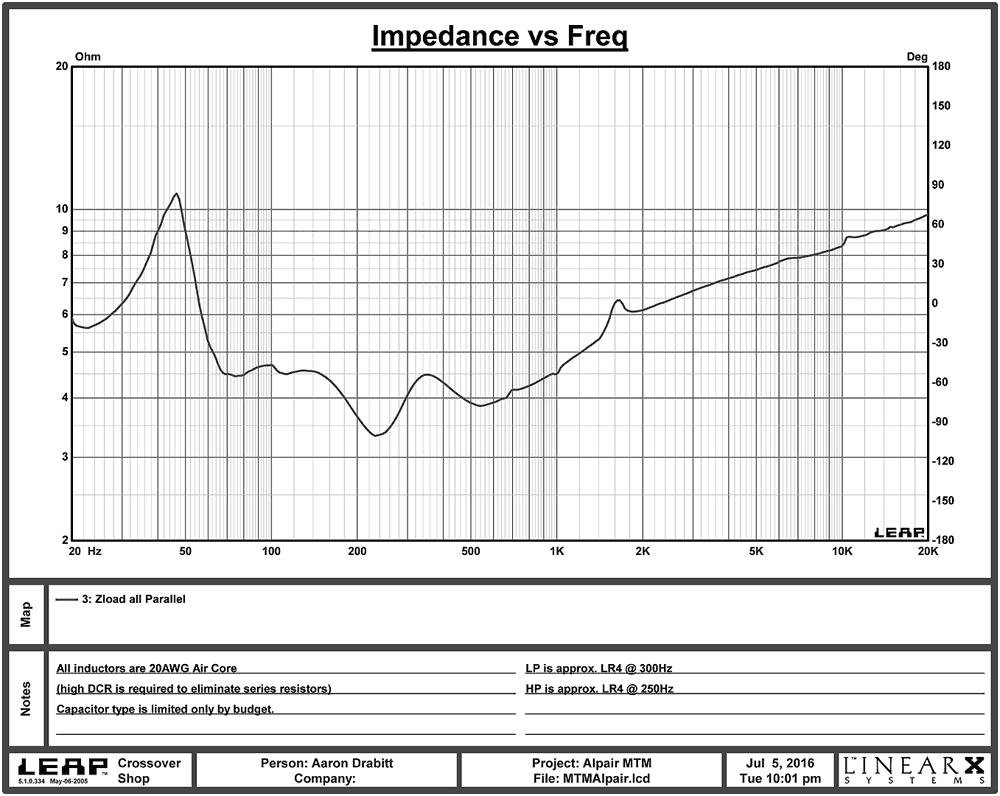
dave
This is the simulated impedance based on real world measures.
dave
- Home
- Loudspeakers
- Full Range
- Alpair 12pw/7.3/12pw MTM