The Vishay Siliconix PBF (first one) is what we use and we know it works. The nPBF is Infineon and has some different spec in areas like parasitic capacitance. Probably an excellent equivalent type but better avoid it just in case the circuit will not like some detail when you can still get the Vishay.
Heatsinks
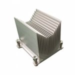
I came across these whilst reading the Xmas TDA7293 thread and having nearly completed my Ubibs but not having decided on sinks yet. I thought these might do the trick and I can get them cheap enough.
They have a gross volume of approx 4"^3....ie 4x4x4 inches minus the cutouts obviously. They are a Dell CPU cooler .
Do you think these have enough thermal mass? Assuming I'm not pushing the Ubib to the max. I would hope to mount one M1 and M2 on one HS.
Attachments
Last edited:
You have to estimate M1+M2 dissipation for the particular setting against the published or calculated thermal capacity of the sink
Heat Sink Size Calculator
Heat Sink Size Calculator
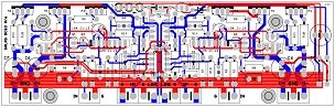
Thanks. Can you show your UBiB board trace? as you did with the DCG3 board. Or is it a trade secret?
You can see general design photos in post #7
Need help...
I have built the Salas 1.3 regulator for 5V from the kit to feed the USB input of my DAC. When I feed the board with 10V from a battery, the sound is great. However, when I feed the regulator by a 15V switching brick for a laptop, I can hear a high pitch tone in the speakers between songs.
When I connect a digital o-scope through a 10uF capacitor to the output on a 100-Ohm load, I see a mostly random high frequency noise of about 20mV with batteries, slightly higher with the switching brick.
I believe this regulator's noise should be at the uV level. Is my build unstable, am I measuring or doing anything else wrong? This is my first regulator build with no prior experience. I would really appreciate any help or advice. I can provide more info, if needed. Thank you!!!
PS. I connect the input DC after the rectifier bridge to Rf; C1 is 6800uF 35V Nichicon LKG (audio grade); R1 = 1.5-Ohm.
Last edited:
It could be something going unstable indeed when fed from the SMPS, since there's no high pitched sound when fed from the battery. Are there any extras installed, like the bridge diodes and the Quasimodo parts? If yes, remove them. In case the SMPS doesn't like a big C1 value you can even replace the 6800uF with 100uF. When DC fed, C1 is mainly for decoupling.
Oscillation is usually a sawtooth like or sine wave like riding waveform with a steady very high frequency. Is that digital scope capable of MHz analysis? Or is it just software for the computer's soundcard?
Usual benchtop DSOs are 8 bit depth dynamic range limited and much wider than audio band. So self noise spec isn't for deep analysis but still giving visual clues. You can compare the line thickness when powering down the reg. If it becomes much thinner, obviously there was something added. They also have AC coupling mode and 20MHz bandwidth limit in their channel menu.
Testing an LC filter for bib in Duncan PSU designer gives error 'timestep has fallen below minimum threshold' , the help button on this does nothing... any ideas what this means?
I chose higher ESR inductors (2.8R 3.9mH) anyway to minimise risk of ringing. Maybe it's already safe enough but it's only guess work so better safe than sorry.
I chose higher ESR inductors (2.8R 3.9mH) anyway to minimise risk of ringing. Maybe it's already safe enough but it's only guess work so better safe than sorry.
Need help...
I have built the Salas 1.3 regulator for 5V from the kit to feed the USB input of my DAC. When I feed the board with 10V from a battery, the sound is great. However, when I feed the regulator by a 15V switching brick for a laptop, I can hear a high pitch tone in the speakers between songs.
When I connect a digital o-scope through a 10uF capacitor to the output on a 100-Ohm load, I see a mostly random high frequency noise of about 20mV with batteries, slightly higher with the switching brick.
I believe this regulator's noise should be at the uV level. Is my build unstable, am I measuring or doing anything else wrong? This is my first regulator build with no prior experience. I would really appreciate any help or advice. I can provide more info, if needed. Thank you!!!
PS. I connect the input DC after the rectifier bridge to Rf; C1 is 6800uF 35V Nichicon LKG (audio grade); R1 = 1.5-Ohm.
I have a same issue, only on the Neg regulator, I feed AC, I have a Quasimodo (47ohm/10n/100n) all of that (Two 5V pos One 5V Neg) R1 1,2ohm.
The two pos reg is stabile.The noise not higher than the scope noise
The neg has 33MHz waveform 15-20mVPP
Thanks
Last edited:
I would look at the input CCS to see if that is oscillating.
I think it would be better to copy the positive shunt circuit to use in the negative version since the shunt circuit is just a 2-terminal block and should work no differently in the negative version with the correct polarity. This way you don't double the effort to troubleshoot problems by creating a new circuit just to use NPN and P-channel MOSFETs.
I think it would be better to copy the positive shunt circuit to use in the negative version since the shunt circuit is just a 2-terminal block and should work no differently in the negative version with the correct polarity. This way you don't double the effort to troubleshoot problems by creating a new circuit just to use NPN and P-channel MOSFETs.
Salas, how you think, is it usefull to power this DAC on ES9018:
ES9018 USB DAC - Hi-Resolution System
with several your UltraBib boards (skiping DACs input DC bridge)?
DAC output stage works in current mode.
ES9018 USB DAC - Hi-Resolution System
with several your UltraBib boards (skiping DACs input DC bridge)?
DAC output stage works in current mode.
hi folks,
can someone please guide me, because I am new to diy... : can I power an amanero usb board (or a singxer f-q usb board) with a 1.3 ultrabib, or should I use a salas reflector-d? (I have a spare 1.3, so this would be my choice, if possible...)
thanks in advance!
can someone please guide me, because I am new to diy... : can I power an amanero usb board (or a singxer f-q usb board) with a 1.3 ultrabib, or should I use a salas reflector-d? (I have a spare 1.3, so this would be my choice, if possible...)
thanks in advance!
- Home
- Amplifiers
- Power Supplies
- Salas SSLV1.3 UltraBiB shunt regulator