#7720 "It should be noted that the direct coupling arrangement of the phase splitting means 20 to the push-pull amplifier means 40 is different than the conventional capacitor coupling usually found in such arrangements. "
GNFB: "All of the output is supplied to the output terminal 65, while a significant portion of the output voltage is sup plied to the feedback transistor 12 via a feedback connection that includes a feedback resistor or current limiting resistor 67 which aids in comparing the output signal at the output terminals 65 with the input signal at the base 13 of the transistor 12. The feedback connection via the resistor 67 to the emitter .18 of the transistor 12 enables the input signal to the amplifier assembly to be compared with the output signal of the amplifier assembly. .This comparison will bias the transistor int-o heavy or low conduction dependent on whether the ditference between the output signal and input signal is large or small. From this it can be seen that the output produced at the collector 16 will maintain the equality between the input signal and the output signal of the amplifier assembly.
Alternatively the transistor 12 may be regarded as a variable impedance element that is connected to the input terminals of the amplifier assembly, to the output terminals of the amplifier assembly and to ground. This variable impedance feedback connection via this solid state element 12 is a significant aspect of the invention that enables the amplifier assembly to drive a very low impedance source such as an impedance having a value of 1 ohm or less."
US3246251A - Low output impedance feedback power amplifier
- Google Patents
Last edited:
TIP3055 is an interesting choice. As best I know it's not a 2N3055E or H. The heat sink might need to be slightly larger to help it.
.
Of the available and not too expensive a good choice I think is BD911, of course you can try 2SD1047, but they cost 2x more...
My whole philosophy is as few active devices between signal sources and speaker. This is a way. I have a little class D amp that works exactly this way. PAM8406.
Hi Nigel, what is your opinion on PAM8406? I have a "premium" board with added filters, film caps etc. and I think it is OK (for its price, simplicity etc).
If you like few active devices between sources and speaker an FDA is an option 🙂
Nigel - The TIP3055 is probably a good choice, and while it may not be a 3055E, it is quite quite close. The 2N3055E was brought out sometime around the time when RCA moved to the epi process. Possibly by Motorola as a variant of the 2N3055. The ft's are similar (2.5MHz for the E, as it is now, without the E though) and 3MHz for the TIP. Or was, ST don't seem to tell us on the current datasheet.
The 2n3055 was pushed to its limits and past in the 1980's.
I built a Maplin disco 225WRMS amplifier with 2n3055/mj2955 running off +/-55 VDC !
I believe they used a higher voltage model but even then it was being pushed hard.
I built a Maplin disco 225WRMS amplifier with 2n3055/mj2955 running off +/-55 VDC !
I believe they used a higher voltage model but even then it was being pushed hard.
Hi Nigel, what is your opinion on PAM8406? I have a "premium" board with added filters, film caps etc. and I think it is OK (for its price, simplicity etc).
If you like few active devices between sources and speaker an FDA is an option 🙂
I use it as my sound bar with TEAC LS-X8. Surprisingly good bass and loud for 1.7 watts. The specs look like a class A amplifier circa 1965 ( Sugden A21 ? ). I added a high grade 10 uF supply decoupling capacitor. The TEACs are a treasure. Also sold as JVC and Radio Shack Minimus. In some ways better than the BBC LS3/5A. Very open and no obvious boom. The little graph on the box side looks impossible for the size, that is until you hear them. I had to fit new roll surrounds. LS-X7 have rubber surrounds which is more durable.
PAM8406 benefits from a high value ultra low ESR cap (which can be small as a 6.3 or 10V version is enough). I used 470 µF. Remarkable performance for such a non HiFi device.
Nigel - The TIP3055 is probably a good choice, and while it may not be a 3055E, it is quite quite close. The 2N3055E was brought out sometime around the time when RCA moved to the epi process. Possibly by Motorola as a variant of the 2N3055. The ft's are similar (2.5MHz for the E, as it is now, without the E though) and 3MHz for the TIP. Or was, ST don't seem to tell us on the current datasheet.
I remember John Dawson of Arcam telling me how nice they are in 1978/9 I bought A60 Sno 301. What a lovely amplifier. Mostly a Sinclair Z50 with TIP3055. Bias as Sinclair.
Low-power JHL69
This is my first excursion into Class A land. Am building a pair of JLH69's tailored to drive a set of xfmr-coupled electrostatic headphones. Would like to scale back the power as much as possible, without sacrificing performance, to minimize heat generation. I ordered a couple of the TIP41C-based kits but they won't arrive for another week or two. These just arrived:
GHXAMP Hifi JLH 1969 Amplifier Audio Class A Power Amplifier Board Stereo High Quality For 3 8 inch Full Range Speakers 2pcs|Amplifier| - AliExpress
Load is pretty easy to drive, around 20 Ohms up to 5kHz. 5VRMS is enough to drive them to comfortably-loud levels, so maybe 8-10V for some headroom. Power-wise we're looking at 5 watts max. I was thinking a 24V supply since I have some of them here.
What changes would you make to the basic circuit to scale it down for 24V, 5W, 20 Ohms? JLH's suggestions for 15 Ohms are for maximum power (37V supply).
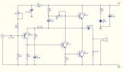
I've attached the schematic for the unit.
BTW, gain curves on the supplied small-signal devices (2N2907A and 2N1711) look good on the curve tracer, very linear parallel lines. Hfe on the supplied 3055's are all over the map. Supplied capacitors are cr@p.
This is my first excursion into Class A land. Am building a pair of JLH69's tailored to drive a set of xfmr-coupled electrostatic headphones. Would like to scale back the power as much as possible, without sacrificing performance, to minimize heat generation. I ordered a couple of the TIP41C-based kits but they won't arrive for another week or two. These just arrived:
GHXAMP Hifi JLH 1969 Amplifier Audio Class A Power Amplifier Board Stereo High Quality For 3 8 inch Full Range Speakers 2pcs|Amplifier| - AliExpress
Load is pretty easy to drive, around 20 Ohms up to 5kHz. 5VRMS is enough to drive them to comfortably-loud levels, so maybe 8-10V for some headroom. Power-wise we're looking at 5 watts max. I was thinking a 24V supply since I have some of them here.
What changes would you make to the basic circuit to scale it down for 24V, 5W, 20 Ohms? JLH's suggestions for 15 Ohms are for maximum power (37V supply).
I've attached the schematic for the unit.
BTW, gain curves on the supplied small-signal devices (2N2907A and 2N1711) look good on the curve tracer, very linear parallel lines. Hfe on the supplied 3055's are all over the map. Supplied capacitors are cr@p.
Attachments
I wouldnt make any changes at all.
I have the jlh 1996 version and it runs at various voltages fine so long as dc offset and standing current are set right for each voltage.
I have the jlh 1996 version and it runs at various voltages fine so long as dc offset and standing current are set right for each voltage.
Interesting, OK. I'll give it a go as-is.
I'm trying to figure out if you're up late or up early 🙂
I'm trying to figure out if you're up late or up early 🙂
Up late as usual. Usually get to bed about 3 to 4am.
Mine is split rail so dc offset is important.
Yours isnt so not a problem.
Mine is split rail so dc offset is important.
Yours isnt so not a problem.
I'm jealous, I typically run out of steam @ 10pm or so. And up early.
Yes, I don't have a problem with the large output caps. The axial ones typically become inductive a bit above 20kHz, obviating the need for an output isolator.
Yes, I don't have a problem with the large output caps. The axial ones typically become inductive a bit above 20kHz, obviating the need for an output isolator.
You need to use an additional heatsink.
To reduce the mains hum / noise, it is advisable to power the amplifier from a linear stabilizer or capacitance multiplier. Use C-R-C filters.
Avoid earth loops during installation.
There is a special board JLH for headphones ($20). Just add a transformer and box🙂
To reduce the mains hum / noise, it is advisable to power the amplifier from a linear stabilizer or capacitance multiplier. Use C-R-C filters.
Avoid earth loops during installation.
There is a special board JLH for headphones ($20). Just add a transformer and box🙂
Last edited:
Thanks, OldDIY! These historicals and tutorials are useful.
But what about some original paper or patent?
US3246251
To reduce the mains hum / noise, it is advisable to power the amplifier from a linear stabilizer or capacitance multiplier. Use C-R-C filters.
I have some Lambda modular 24V supplies laying around, I plan on using one or more of them.
There is a special board JLH for headphones ($20). Just add a transformer and box🙂
I have one of those kits coming, it will be good for dynamic headphones, but it's not suitable for driving these electrostats (5 Watts).
You might find hum and hiss noticeable.
Is this a noisy amplifier? I don't recall that being mentioned.
- Home
- Amplifiers
- Solid State
- JLH 10 Watt class A amplifier