When the offset was lowest (4.5mV) the voltage at pin 6 of the servo op amp was 169.1 mV
measured between pin 6 and the grounded corner of the board.
measured between pin 6 and the grounded corner of the board.
Good to hear you got it up and running Turion. Interesting apprach with the RCA ground to PSU star? 15mV is still within reasonable limit for speakers - but that is odd that it is not closer to 5mV. You can try changing R15 to 10k and that is still a safe value according to Jhofand. That will give you some more gain on the feedback loop to zero it out.
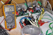
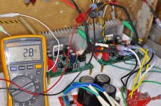
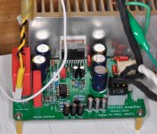
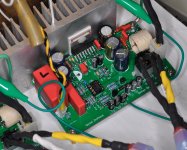
X: I replaced the 47K5 at R15 with a Dale CMF55 10K (its what I had in my stock) and the DC offset at output dropped to 3.5 & 3.8 mV DC (see pics).
Hi Pete,
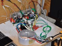
Can you post pics of your setup showing how your psu and amp boards are wired? Strange that you had to move the signal gnd to the psu?
Vunce: I took apart all the ground wiring and re-connected everything. I took the boards’ GLB directly into the Earth star ground and re-connected the input signal ground to the RCA connector. Ground loop feedback eliminated. I may have grounded the boards’ GLB outputs to the PS star ground last time. All good now!
Thanks to both of you for comments/suggestions.
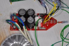
All of the X5R caps are mounted under the board in case I wanted to change them out.
Pete
Attachments
-
 A7790F03-99AB-4E1B-B71E-E978F2DCB264.jpeg447.3 KB · Views: 340
 -
 30A2B54B-F8EE-4A8C-876D-99675D5EE397.jpeg427.4 KB · Views: 330
 -
 6ADF735B-8D64-4EE1-8DF0-DBA4F42D775D.jpeg437.4 KB · Views: 331
 -
 9AB91BEB-013A-4455-949A-97BBC925F739.jpeg363.9 KB · Views: 324
 -
 17AAA0A0-2088-4670-BA9C-F6C593C6B304.jpeg436.5 KB · Views: 337
 -
 0B4E1E6F-8471-449D-88C5-9604156A80DF.jpeg431.4 KB · Views: 230
Last edited:
Well done, Pete!
Please post litening impressions when the time is right, can't wait to read you 🙂
Claude
Please post litening impressions when the time is right, can't wait to read you 🙂
Claude
Just out of curiousity, is there a trade off going directly to the lower resistance value in the DC servo?
I understand it could work harder, and there are limits to values re stability etc., but does one impact sonic qualities going 10kR?
I understand it could work harder, and there are limits to values re stability etc., but does one impact sonic qualities going 10kR?
Last edited:
Fantastic Pete!!
Proper grounding is key to a fully satisfactory project 😉
BTW, this amp is silent at idle, can’t tell it’s on.
Enjoy some music now!!😀
Proper grounding is key to a fully satisfactory project 😉
BTW, this amp is silent at idle, can’t tell it’s on.
Enjoy some music now!!😀
Last edited:
The bottom is amazingly deep with the 680pF (instead of the 220pF) in combo with the WIMA 4.7uF MKP... Have to let them burn in a bit..
Pete
Pete
Hi turion64 (Pete),
When you posted about using IC sockets for U4, where you referring to the solderless type, as the holes on the pcb are close together and harder to solder. Just wondering as a soldered socket is no advantage, except for removal of the IC.
MM
When you posted about using IC sockets for U4, where you referring to the solderless type, as the holes on the pcb are close together and harder to solder. Just wondering as a soldered socket is no advantage, except for removal of the IC.
MM
Hi turion64 (Pete),
When you posted about using IC sockets for U4, where you referring to the solderless type, as the holes on the pcb are close together and harder to solder. Just wondering as a soldered socket is no advantage, except for removal of the IC.
MM
Your last sentence is the winner! I wanted to be able to easily replace the single op-amp in either the case where something shorts it or i want to try other op-amps at the heart of the servo.. just because.
Pete
Qyick one guys if I may. I didn't get on this benevolent 'GB' but I'm happy to have some PCB made if thats OK with XRK....for use within these walls obviously.
Is the 2 oz copper a must for the boards or is 1 oz ok.
Cheers!
Is the 2 oz copper a must for the boards or is 1 oz ok.
Cheers!
@Turion - Fatastic work! Glad it’s all quiet now and DC offset is low. Enjoy the music!
@Jimk - Feel free to make boards and offer to others in this thread. This was meant to be an open project for all to enjoy. I am told the amp will work fine with 1oz copper as the traces were sized wide enough. However, I would get 2oz for durability in case one needs to remove and reinstall parts. It’s $18 extra I know, but worth it in my opinion. The ENIG is purely cosmetic here as we have no SMT parts. But the boards I gave away had the full treatment 2oz plus ENIG.
@Jimk - Feel free to make boards and offer to others in this thread. This was meant to be an open project for all to enjoy. I am told the amp will work fine with 1oz copper as the traces were sized wide enough. However, I would get 2oz for durability in case one needs to remove and reinstall parts. It’s $18 extra I know, but worth it in my opinion. The ENIG is purely cosmetic here as we have no SMT parts. But the boards I gave away had the full treatment 2oz plus ENIG.
My impressions so far? With the following build variations in place and listening with 8 ohm speakers (Genesis Physics 210 speakers ..680pF WIMA at C10, 10pF C0G across R1, 4.7uF WIMA MKP4 in C201, 1uF WIMA MKP4 in C127, 10K Vishay/DALE CMF55 at R15, 24000uF per rail (Nichicon LKS 50V)...a wonderfully warm sound with a deep, satisfying bottom to the music. Spacial soundstage. A bit more "sparkle" in the upper frequencies would be nice so something to look at (R1, R3; maybe R4 and/or R9?). A pleasing sounding chipamp. Kudos to the designers.
Anyone else?
Cheers Pete
Anyone else?
Cheers Pete
Last edited:
Hi Turion64,
Have you had a chance to listen with some real speakers yet? Curious as to what your impressions are.
Have you had a chance to listen with some real speakers yet? Curious as to what your impressions are.
Hi Pete,
Excellent results then 🙂
Would be delighted to hear your comparo with your Class D amps 🙂
Regarding the sparkle... I don't know if tweaking the resistors can make any real difference... but what about a quick test, just adding some small caps as bypasses to C12, C13, C14 and C15? If you still have some of the small Murata 0.082uF C0G on hand, easy to install and uninstall under the board / between the legs of teh existing main cap, that could be a quick check to see if the sound moves in the direction you want...
Have fun and thanks for the feedback
Claude
Last edited:
The Genesis Physics are the "real" speakers X.
Pete
Oh sorry Turion, when I was writing my post I hadn’t seen your post yet - my mistake. Thanks for the listening impressions. Sounds like a good amp then. Sparkle might be what some amps offer because they have higher third order harmonic distortion which sounds sharper or has more “bite”. I noticed that at higher power, the amp has higher third harmonic. When you listen at louder volumes, do you hear more sparkle? One way to replicate this is to add say a 50w 8ohm load resistor in parallel to your speaker. Thereby making the amp drive a 4ohm load. This will increase third harmonic and perhaps add sparkle or bite. Just as a test - not to be used permanently of course. Or switch to 4ohm speakers.
Ah, indeed depends on what kind of "sparkle"... I was more thinking treble extension, perhaps wrong then... Bypass caps won't really help more rawness / bite, if that's the point
Fascinating
Claude
Fascinating
Claude
My impressions so far? With the following build variations in place...
Thanks Pete for posting your impressions and summarizing the variations you made/used.
Almost 500 posts, it's somewhat difficult to follow the changes from the original post.
The Genesis Physics are the "real" speakers X.
Pete
Isnt Genesis started by Arnie Nudell? He is literally one of the most legendary speaker designer. I once heard Infinity RS IIIa , Man i was blown for such a old speaker.
Last edited:
Planning for the 680pF cap at C10, the 4.7uF cap at C201, 1uF cap at C127, Dibya's (special sauce) 100uF Silmic II for C5 and C11.
No plans for 10pf across R1, I don't think my ears are good enough to tell.
Is R15 a guessing game, trial & error so to speak, or should one use the 47.5K if not making any changes and the 10K if mods used like Pete used ?.
MM
No plans for 10pf across R1, I don't think my ears are good enough to tell.
Is R15 a guessing game, trial & error so to speak, or should one use the 47.5K if not making any changes and the 10K if mods used like Pete used ?.
MM
Not the same "Genesis" trip I am afraid, but nice vintage LS
HUMAN Speakers: The Genesis Story
Claude (Infinity aficionado)
HUMAN Speakers: The Genesis Story
Claude (Infinity aficionado)
- Home
- Amplifiers
- Chip Amps
- Xmas Amp - Dibya's TDA7293 by Jhofland