Long battles have been fought over the grounding of amps... My own amps have been silent with speaker ground return to the PCB. There is a wealth of info on hifisonix 's website.
Star grounding is a good start.
Earthing the zero volt line helps if no other earth in system to loop with.
Thank you for sharing the wonderful project, I have had the PCBs made and assembled amplifier boards. Currently I am using the chipamp power supply board and everything works fine.
However I would like to use the power supply board suggested by 00940. I have gone through the thread many times but I cannot find the values of R1.2.4.8 and C9,10,11,12 for power supply PCB.
The PDF BOM shared earlier in the thread is without the part numbers and as a novice I do not want to risk it, so I would appreciate any help.
Thank you in anticipation
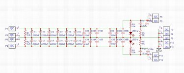
R3-R4 are resistors for the led indicators (if wanted). Their value depends on your rail voltage and the led used. Something like 10k would do in most cases I guess.
The other caps/resistors are there to allow snubbers. Honestly, I don't use them at all in my build. If you search for snubbers, transformers, diodes, you'll find many threads discussing the issue.
The other caps/resistors are there to allow snubbers. Honestly, I don't use them at all in my build. If you search for snubbers, transformers, diodes, you'll find many threads discussing the issue.
The filter on the front end has a breakpoint of 400,000Hz.
That could come down quite a bit.
Yes, but the board was intended to work straight from a 10k pot. If driven by a low impedance, you can indeed lower the filter frequency.
R3-R4 are resistors for the led indicators (if wanted). Their value depends on your rail voltage and the led used. Something like 10k would do in most cases I guess.
The other caps/resistors are there to allow snubbers. Honestly, I don't use them at all in my build. If you search for snubbers, transformers, diodes, you'll find many threads discussing the issue.
Thank you so much , in that case I’m already done.
Best wishes
Since there is a gnd output for the speaker on the pcb, I connected the speaker there..
So, I conected the PSU 0 output to speaker gnd instead of the amp output gnd and the hiss issue improved. After placing the amp and the psu (linear) farther from the transformer (>30cm) the hiss was not audible anymore. Though, if i put my ear close to the speaker i can hear the hiss again (same 91dB speaker) - which is acceptable. Otherwise, I can say the sound is good. Thank you! (especially to 00940)
I can't recall now, I just sticked with the schematic markings.-selwe: what did you use as value for the mute resistor and on which voltages do you run the amp ? Do the chips get hot ?
The smps are 2x24V (in series) and the linear one is 2x21V.
The hottest temp after running 2 hours, as measured by a Caterpillar Flir cam, was around 45 deg. Celsius.
I decided it's worthy to put together a compact stereo and a 10K pot (conductive plastic) will be installed in the end. Hopefully, I' ll put some nice pictures one day
Last edited:
Very cool, good work!So, I conected the PSU 0 output to speaker gnd instead of the amp output gnd and the hiss issue improved. After placing the amp and the psu (linear) farther from the transformer (>30cm) the hiss was not audible anymore. Though, if i put my ear close to the speaker i can hear the hiss again (same 91dB speaker) - which is acceptable. Otherwise, I can say the sound is good. Thank you! (especially to 00940)
This motivates me even more to quickly redo my PSU which is prototyped on stripboard with very thin conductors.
The amp sure sounds very good and the PCB is nice and compact.
G'day Guys,
Here is a PSU I designed to use with gainclones and other smaller SS amps.
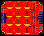
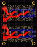
Dual rectifier board

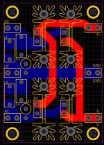
Single rectifier board
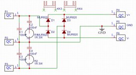
The idea here was to use a bunch of smaller caps 5-7.5mm pitch and up to 18mm diameter for 'high speed' and low ESR compared to larger 10000uF types typically used. eg: 12x 2200uF.
-Snubbers on the outputs
-Indicator leds
-Options for bypass caps across the filter caps from 2.54mm up to 20mm, ideally something like a 2.2uF film cap and a 100nF ceramic type.
Options for a dual rectifier for a tranny with dual secondaries or a single rectifier for a tranny with a centre tap. Both with snubbers on the transformer secondaries.
Due to space constraints I would recommend ordering the rectifier boards with 2oz copper for higher current handling, I couldn't get the tracks wider than 4mm. Unless of course only low current is required.
The filter board should be fine with 1oz copper due to the massive pours however 2oz copper would be even better for lower impedance.
I am yet to test this iteration as they are getting fabbed by JLC right now however I don't foresee any issues.
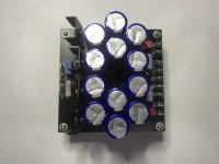
Here is a photo of the previous iteration with 12x3300uF. This version had the rectifiers on board.
Gerbers attached.
Here is a PSU I designed to use with gainclones and other smaller SS amps.


Dual rectifier board


Single rectifier board


The idea here was to use a bunch of smaller caps 5-7.5mm pitch and up to 18mm diameter for 'high speed' and low ESR compared to larger 10000uF types typically used. eg: 12x 2200uF.
-Snubbers on the outputs
-Indicator leds
-Options for bypass caps across the filter caps from 2.54mm up to 20mm, ideally something like a 2.2uF film cap and a 100nF ceramic type.
Options for a dual rectifier for a tranny with dual secondaries or a single rectifier for a tranny with a centre tap. Both with snubbers on the transformer secondaries.
Due to space constraints I would recommend ordering the rectifier boards with 2oz copper for higher current handling, I couldn't get the tracks wider than 4mm. Unless of course only low current is required.
The filter board should be fine with 1oz copper due to the massive pours however 2oz copper would be even better for lower impedance.
I am yet to test this iteration as they are getting fabbed by JLC right now however I don't foresee any issues.
Here is a photo of the previous iteration with 12x3300uF. This version had the rectifiers on board.

Gerbers attached.
Attachments
Last edited:
Cool offer sadface but I already ordered PSU PCBs.
Yours look relatively big?
Always on the look out for something small, like 100x50mm max incl. rectifier, ground-breaker and optional regulators.
Yours look relatively big?
Always on the look out for something small, like 100x50mm max incl. rectifier, ground-breaker and optional regulators.
Gain
Hi Guys,
I am having a bit of difficulty getting my head around the gain on these boards.
Specifically the interactions of R5, R7 and C5.
I understand that R7 and C5 are supposed to reduce gain at high frequency.
With the values specified on the schematic, R5: 22k, R7: 22k and C5: 47pF. What is the gain?
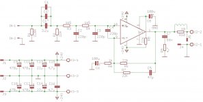
My mind wants to view R5 and R7 as being in parallel making an 11k resistor between the pair of resistors for a gain of 12x (Av = (R1+R2)/R2)
Am I correct here?
Hi Guys,
I am having a bit of difficulty getting my head around the gain on these boards.
Specifically the interactions of R5, R7 and C5.
I understand that R7 and C5 are supposed to reduce gain at high frequency.
With the values specified on the schematic, R5: 22k, R7: 22k and C5: 47pF. What is the gain?

My mind wants to view R5 and R7 as being in parallel making an 11k resistor between the pair of resistors for a gain of 12x (Av = (R1+R2)/R2)
Am I correct here?
Last edited:
So, I conected the PSU 0 output to speaker gnd instead of the amp output gnd and the hiss issue improved. After placing the amp and the psu (linear) farther from the transformer (>30cm) the hiss was not audible anymore. Though, if i put my ear close to the speaker i can hear the hiss again (same 91dB speaker) - which is acceptable. Otherwise, I can say the sound is good. Thank you! (especially to 00940)
Can anyone explain why this might be? I was originally thinking maybe he has other electrical equipment nearby that are injecting noise into mains, which thorough the power supply is coupling into the output as common mode noise. So I was going to suggest to perhaps move his set up to another room or use a mains filter like a common mode choke and x caps. But it seems this could be something different. As he is moving the amp away from the transformer, the hiss improves. Could it be caused by EMI/RFI from mains wiring or other devices or something else?
If it helps, I posted an analysis of the feedback network >here<
As you say, the high-frequency gain will be ((22k||22k)+1k)/1k = 12
Many thanks.
The math's goes a bit over my head sadly. Transfer functions are beyond me at this stage.....
If my desired gain is 12x and the minimum gain for stability is 10x
((11k||50k)+1k)/1k = 10.01x.
Which begs the next question, is it worth trying to decrease the gain by such a small amount or should I simply omit r7 and c5 for a simpler implementation with 12x gain across the spectrum?
Last edited:
I have no experience of LM3886 applications, so I may be missing some important considerations that the more experienced will know, but purely from a datasheet review, the example application circuit shows an in-band gain of x21, optionally reducing to x11 at high frequencies. So on that basis, I'd say that if you set the in-band gain to x12, then a high-frequency gain reduction is probably not required.Many thanks.
The math's goes a bit over my head sadly. Transfer functions are beyond me at this stage.....
If my desired gain is 12x and the minimum gain for stability is 10x
((11k||50k)+1k)/1k = 10.01x.
Which begs the next question, is it worth trying to decrease the gain by such a small amount or should I simply omit r7 and c5 for a simpler implementation with 12x gain across the spectrum?
Thanks Rich,
Our thinking is in the same direction which is hopefully a sign I'm on the right track.
Our thinking is in the same direction which is hopefully a sign I'm on the right track.
Gain of 12 sounds good to me; or anything above 10.
Let us know how it works if you have a chance to measure or validate stability.
Am thinking of reducing gain on my amps too.
Let us know how it works if you have a chance to measure or validate stability.
Am thinking of reducing gain on my amps too.
- Home
- Amplifiers
- Chip Amps
- An open source layout for LM3886?