I strongly recommend REW for noise measurements. Or any other audio related measurement.
I would like to try that as well. Any documentation that would make it easier to get into? Can I set my 0dB point in REW?
If the denoiser offers -35dB over the -20dB of Cadj, then that means 600nV, which from 1.3V means almost -127dB.
Assuming that denoiser brings a 30 or 35 dB improvement is not the correct method. Improvement should be measured precisely. For that, one should calibrate his measurement gear by bottom – up method.
First, exact LNA noise floor should be determined using short circuit at the LNA input and then using variable resistor at the input, as noise source, to increase short circuit value by + 3 dB. Measured resistance, for getting +3dB increase, has exact equivalent input noise of LNA, so this is our LNA noise floor. Now, we can adjust displayed level in the used software to the correct value and confirm a point or two using known noise of several resistors as 1 kΩ or so.
Additionally, we can apply some small signal at the LNA input, measuring exact value with good RMS multimeter and confirm that level displayed by our measurement SW corresponds. That would be enough good calibration procedure for our DIY needs.
I would like to try that as well. Any documentation that would make it easier to get into? Can I set my 0dB point in REW?
Not only for the distortion measurement. REW is a very powerful SW.
Howto - Distortion Measurements with REW
A lot about noise measurement problems by one forum member in the DAC thread:
https://www.diyaudio.com/forums/digital-line-level/314935-es9038q2m-board-649.html#post6490007
The main scope of making this LNA was for differential measurements so I know if the denoiser works or not. Been very helpful this way so far. I don't really trust the absolute values as they are not really of much use to me. I get more use out of seeing if the denoiser is working or not, and testing enough different applications of the denoiser, I got a sense of where the levels should be. That is good enough for implementing, but clearly not good enough to have an absolute value battle with other calibrated devices.
The noise capability of this circuit has been measured already with better tools by the creator of the circuit, there's no need for me to add to that.
RickRay has the same LNA as I do, and his 0dB point is 8dB higher than mine based on his audio card specs. Hence why I said it's about where I see the denoiser values.
I may try at some point to calibrate the absolute values for the LNA, but that isn't of much interest for me really. The most use I get out of it is seeing if there's any real issues with the denoiser when I make a pcb.
edit: the LNA is based on one of Douglas Self's moving coil preamp designs. Tested the gain and was within 0.2dB or so of 60dB. Simulation for the circuit shows ~0.4nV/sqrtHz noise.
Last edited:
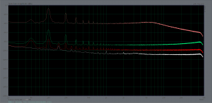
Here's measurements for simple LM317 without Cadj, LM317 with denoiser, with dienoiser, and last trace is my LNA's input shorted at the cable end where I sense the output of the LM317 pcb. This is enough to tell what's happening, without needing absolute values.
Also as you notice the noisefloor is reduced the same as the ripple. That is good, that is what you want when you add the denoiser. When the ripple is not being attenuated the same as the noisefloor then there's something that's not optimal.
edit: the 60dB gain of the LNA is not included on the ARTA scale, so add -60dB to it.
Attachments
These types of measurements maybe useful to you but useless for most of us as they are not comparable to measurements made by others or to datasheets. Also regarding ripple the 2 topmost graphs have almost the same ripple so where is the 30db ripple reduction?
Also regarding ripple the 2 topmost graphs have almost the same ripple so where is the 30db ripple reduction?
Exactly! They look almost the same. The ripple reduction is the difference in value on the left for each 100Hz signal. That is the denoiser vs simple LM317 reduction, in ripple and also in noisefloor. That is the idea. See how relative measurements help? We don't need the absolute value, we need to trust that the ADC can reliably measure a 30dB span. Even if its off by 1-2dB, still good enough to tell if the denoiser works as it should.
A working denoiser, if you measure at the denoiser's point of sensing, should give the full 30dB of noisefloor reduction vs Cadj, or around 50dB noisefloor reduction vs simple LM317.
If there's anything not optimal with the implementation, and the denoiser is working, the noisefloor is 30dB (vs Cadj) or 50dB (vs simple LM317) lower, but PSRR suffers. At least that's what I observed so far.
The idea is that when the denoiser or dienoiser are working, they reduce the ripple (through increased PSRR) and also the LM317 own self-noise which is the noisefloor you see, by the same amount at the same time. Namely around 50dB for denoiser vs simple LM317. Both traces look almost the same, just that the denoiser one is 47dB or so lower. The traces have two components in them, the noisefloor, and the 100Hz ripple signal (and harmonics of that). When both go down the same amount (namely around 50dB for denoiser vs simple LM317) then you know the denoiser is working fine and offering the full performance.
Knowing that the denoiser should lower everything by around 50dB is enough in a relative measurement. No need for accurately calibrated devices. With a LNA you only need your average soundcard that can tell the difference between two signals 50dB apart, in its own dynamic range window. You measure before, and after, and if you see everything 50dB lower (for simple LM317 with denoiser added to it), then the denoiser is working fine. If only the noisefloor goes 50dB lower, but the ripple signal goes 25dB lower only (for example) then there's things that are not optimal in the circuit.
Knowing that the denoiser should lower everything by around 50dB is enough in a relative measurement. No need for accurately calibrated devices. With a LNA you only need your average soundcard that can tell the difference between two signals 50dB apart, in its own dynamic range window. You measure before, and after, and if you see everything 50dB lower (for simple LM317 with denoiser added to it), then the denoiser is working fine. If only the noisefloor goes 50dB lower, but the ripple signal goes 25dB lower only (for example) then there's things that are not optimal in the circuit.
Your measurements may have some value as relative measurements between your DUTs. But they have little value outside your tests especially regarding noise measurements. Noisefloor on your graphs can simply be lowered by increasing FFT length.
It is also easy to see that your noise calculations are way off. Your LNA probably has a noise floor of 0.6 nV/rtHz based on measurements of the same LNA in another thread. So the total noise of that is about 100nV over audio range. Based on your graphs dienoiser is clearly above your LNA so it most definately does not have noise below 100nV. So Tombo56's comment about your measurements being -20dB off is quite accurate.
It would probably take you less than an hour to get familiarized with REW and redo your noise measurements properly.
Yeah but why? I have no real use for absolute values. I don't really care. What do I do with that number? Where is that number useful for me?
If you measure a few LM317, different ones with Cadj and so on, you see where the noisefloor should be on your graphs. Doesn't really matter you're not seeing a calibrated value, it matters that you know what that tool should show you for a normal LM317/denoiser etc.
It's nice to have calibrated tools, but to know if the denoiser is working or not, you don't neet to know the absolute value of the noisefloor.
Since you are publishing your measurements to support your claims to other members it is only common courtesy to make sure that your measurements are done properly.
Yeah but I don't sell any boards. I don't have an incentive to convince anyone of anything.
The way I see it, it's a minimum thing I can do for my designs for anyone making them.
For example, a relative measurement of the VRDN is good enough to confirm my suspicions about the design issues around the denoiser. The positive rail denoiser seems to work but PSRR suffers because of the non-optimal grounding for it, and the negative rail doesn't seem to be working with the denoiser.
Again, if you want to disprove what I show, you build the board I designed, you measured it with calibrated gear, and you show everybody how off my measurements were. That is how you do this.
Also based on your response from post #286 I don't even think you understand the measurement graphs so I don't know why you're arguing about this.
Here you go again with personal insults. That has been your approach whenever you are challenged.
I do hope that other members realize that your measurements have little value.
I do hope that other members realize that your measurements have little value.
I didn't mean it as an insult, sorry if it came out that way. I don't know how else to say it, your response was clear that you didn't understand the graph, I don't know why you are arguing about the measurement without understanding it, that was what I meant to say.
Measurements and physics do not care about opinions. They just are. I think some relative measurements are better than no measurements. You can extract useful information from relative measurements, without calibrated gear.
Measurements and physics do not care about opinions. They just are. I think some relative measurements are better than no measurements. You can extract useful information from relative measurements, without calibrated gear.
Since your graph did not display the input voltage it is fairly difficult to make any sense of the graphs. I do hope you take some time to study how to make these measurements properly.
On the denoiser thread I usually mentioned that my 0dB is at 1.3Vrms. So yes you're right with that. I set it based on the alc892 datasheet that my PC's motherboard has. Might be a non-standard implementation so figures might be off a bit. I mentioned on the denoiser thread at first that these measurements should be taken for the differential value not absolute one. I do understand that I can't claim absolute values with such a simple setup. Nevertheless it's good for extracting useful information. It's more than nothing, and for many things it's good enough.
I think the initial issue was Mark Johnson complaining in the denoiser thread about issues with different types of LM337 that are not stable, somehow implying that the denoiser is not working fine with some LM337 made by certain manufacturers.
My position is that they all work fine, so the issue is most likely in the design of the pcb rather than the denoiser circuit itself.
From my point of view, the denoiser design for this pcb is not optimal. The VRDN board is a solid normal LM3x7 board (rather overkill with the 4 layer design), but it's not an optimal design for the denoiser. I hope he takes this into consideration for the next version, as that would be good for everybody who makes the board, in the end.
For example, a relative measurement of the VRDN is good enough to confirm my suspicions about the design issues around the denoiser. The positive rail denoiser seems to work but PSRR suffers because of the non-optimal grounding for it, and the negative rail doesn't seem to be working with the denoiser.
Again, if you want to disprove what I show, you build the board I designed, you measured it with calibrated gear, and you show everybody how off my measurements were. That is how you do this.
Trileru,
your two last post show a lot of “that’s how it is not done”!
At diyaudio, you don’t use personal insults when challenged. If it was unintentional, then words choice was very unfortunate.
At diyaudio, you don’t discredit someone’s work by claims with no proof that something doesn’t work. Did you actually measure VRDN regulator and what is a value of such measurement in light of your description of used measurement methods?
Valid PSRR measurement is a tricky thing.
Yes as I said I did not mean to insult anyone.
And as you said, when disproving something you have to present a counter measurement. I looked at the only measurement that was made for the VRDN and from my experience with the denoiser I could extract that the positive rail denoiser is working but PSRR suffers because of grounding issues, and I explained my reasoning before any measurement was made. The negative rail doesn't seem to have a well functioning LM337+denoiser, apart from grounding issues. My observations are based on that rather maybe non-ideal measurement, tho I think it's in line with other member's issues with this board. There aren't any wild claims I make, it's pretty consistent.
And as you said, when disproving something you have to present a counter measurement. I looked at the only measurement that was made for the VRDN and from my experience with the denoiser I could extract that the positive rail denoiser is working but PSRR suffers because of grounding issues, and I explained my reasoning before any measurement was made. The negative rail doesn't seem to have a well functioning LM337+denoiser, apart from grounding issues. My observations are based on that rather maybe non-ideal measurement, tho I think it's in line with other member's issues with this board. There aren't any wild claims I make, it's pretty consistent.
Again, an example of how it is not done.
Using someone else's uncalibrated measurement, to make an assessment, has a quality of scientific approach called “rectal extraction method”, how Mark has put it nicely on some other occasion.
No wild claims you say? Yup, there is an another description for that.
Using someone else's uncalibrated measurement, to make an assessment, has a quality of scientific approach called “rectal extraction method”, how Mark has put it nicely on some other occasion.
No wild claims you say? Yup, there is an another description for that.
- Home
- Amplifiers
- Power Supplies
- VRDN: bipolar regulator PCB for line level ckts: ±11V to ±20V @ 1.5A with "De-Noiser"