As things are, sometimes listening preferences do vary quite a bit in the bass department whereas you are listening to a HP or a LS. Conclusions could differ...
As for the DF, beefing up the PS caps at the chip may help... could also give more body / flesh on the bone to the bass... perhaps. And perhaps getting rid of the feeling of light bass?
Last but not least, as posted C10 forms the low pass filter with the 750R. Going for 680pf gives Fc = 312kHz. That's much better than the initial 1MHz. We are getting there, well noting you could still double the caps values to half further the BW... should you need to. That would still be very acceptable (around 160kHz)... I wonder how that would affect the stability and the sound...
For C10, regardless the value one will go for at the end... although not directly in the signal path it is in fact affecting the signal directly, I would go PPP space permitting (or C0G worst case). The initial Wimas were a good choice... so on the other hand if space is an issue on the board not going too high values for C10 might help keeping a good PPP cap. Trade off...
Great to see all this development, great thanks gentlemen!
Claude
My hunch about output impedance was wrong. It's 16-18mOhm through the audio band.
I will restrict posting about my headphones here if you will stop asking about them. My concern is with these amp boards. I already researched TPA6120 options (I have a working board here) and it's a candidate for higher-impedance phones but not for the 'stats.
Since I've asked three times if the tonal impact of the bootstrap cap change was checked, and received no reply, I have to assume that change was made for other reasons and without checking to see if it impacted the sound. I'll experiment with it here.
Dibya can comment on this later (it's night time in India), but he did the testing with the bootstrap caps and did say that the ones he arrived at gave improved bass response. I suspect using a bank of 20x 1000uF caps provides lower ESR and connect that with say 14ga high strand count wire from the PSU to the amp. But I am not sure what else to try - other than make a discrete Class AB amp with a humongous output TO-247 MOSFET. You have to imagine that the impedance through that is going to be whole lot less than the tiny MOSFET inside the chipamp. 🙂
There are Class AB amps that don't have too many more components than this chipamp - they do require double the work mounting the MOSFETs as there are two vs a single chip. For example, I have designed one with 9 actives, and a similar price point BOM-wise, and it will blow away the performance of any chipamp in the musical dynamics and bass authority department.
There are Class AB amps that don't have too many more components than this chipamp - they do require double the work mounting the MOSFETs as there are two vs a single chip. For example, I have designed one with 9 actives, and a similar price point BOM-wise, and it will blow away the performance of any chipamp in the musical dynamics and bass authority department.
Last edited:
OK, thanks. The data sheet gives 22uf as a minimum value for the bootstrap cap, but they give no maximum value. There is an option to tie it to the output pin. I'll experiment with it a bit, that's about all that's left for me. If I can't make this setup perform as well as the 3886 board I got, I'll punt and move on.
No point in connecting bootstrap directly to output.
It will remove bootstrap framework of 7293 which removes bootstrap from signal when not needed.
Unless you cranking the amp over 5vrms , bootstrap will not engage.
Put 22uf bootstrap you will see what is called bad bass.
I did hours of cap rolling.
If you want a proper discrete amp I will recommend FH9 by X.
If you want you can try 47uf too or other values.
I did hours of cap rolling.
OK thanks Dibya. How high a value did you go? Just curious...
I went up to 150uf.
I wont recommend going further as on another forum , ST engineer said not to go higher than 220uf.
This IC is bit low on bass as the primary customer are guitar amp manufacturer so they wanted better highs.
Happy Cap rolling.
Cheers
I wont recommend going further as on another forum , ST engineer said not to go higher than 220uf.
This IC is bit low on bass as the primary customer are guitar amp manufacturer so they wanted better highs.
Happy Cap rolling.
Cheers
OK thanks, good to know. I won't mess with it, then. I'll just stick with the 3886 boards.
If anyone is interested in a couple of these boards with the 7293's and some parts installed, PM me.
If anyone is interested in a couple of these boards with the 7293's and some parts installed, PM me.
If you have listened to LM3875 and LM3886, 3886 do bump the lower frequency and focus more on midrange than 3875 which is flat to my ear.
I'm not using the standard config, the inputs are DC coupled, and no feedback shunt cap either. The DAC has an output cap.
I haven't heard a 3875, I used a PS Audio amp which I've owned for decades on these 'phones until I blew it up by accident while adjusting the bias after recapping it. 🙁 The bass/lower mids on the 3886 board is very much like the PS, I don't find it accentuated. Interesting, both the 7293 and 3886 boards measure flat within 0.1dB from 10Hz up on the network analyzer at 1VRMS out. So this is a difference in dynamic behavior, not freq response, per se.
I haven't heard a 3875, I used a PS Audio amp which I've owned for decades on these 'phones until I blew it up by accident while adjusting the bias after recapping it. 🙁 The bass/lower mids on the 3886 board is very much like the PS, I don't find it accentuated. Interesting, both the 7293 and 3886 boards measure flat within 0.1dB from 10Hz up on the network analyzer at 1VRMS out. So this is a difference in dynamic behavior, not freq response, per se.
Last edited:
May be you like BJT over MOSFET.
How much PSU cap are you using? Higher the PSU cap on the mainboard , sound of 7293 on midrange becomes blurry. Please try just 220uf + 100uf on board psu Cap before moving on.
May be you like H3 dominant sound , try putting Metal film for feedback resistor.
How much PSU cap are you using? Higher the PSU cap on the mainboard , sound of 7293 on midrange becomes blurry. Please try just 220uf + 100uf on board psu Cap before moving on.
May be you like H3 dominant sound , try putting Metal film for feedback resistor.
What's the most probable reason for that »blurry« midrange with bigger PSU capacitors?
Best regards!
Best regards!
LOL, no, my main stereo amp has MOSFET outputs and I like it a lot.
I have 2x 470uF on board. Power supply impedance measures flat 28mOhm to 20kHz at the bypass caps. That's pretty darn good. I'm ok with the midrange.
I appreciate your efforts, but I'm ready to move on. I've got some JLH kits to build and try next.
I have 2x 470uF on board. Power supply impedance measures flat 28mOhm to 20kHz at the bypass caps. That's pretty darn good. I'm ok with the midrange.
I appreciate your efforts, but I'm ready to move on. I've got some JLH kits to build and try next.
Last edited:
What's the most probable reason for that »blurry« midrange with bigger PSU capacitors?
Best regards!
Thats a Mistry I cannot figure out. Still drives me crazy. Even Focus rite soundcard shows similar Harmonic profile yet it sounds different.
I thought i was hallucinating so i called few of my friends for AB Testing, all of them noticed the same.
Have you tried bypassing the bigger caps, say 1500uF, with say an intermediate 4.7uF, of course while having a final bypass cap of say 0.1uF?
I understand this can be a mixed blessing and could bring oscillations etc. but I found that on some units that were overly senstive to PS and not reacting as expected (eg something not optimal elsewhere) it could be worth a try.
Provided it is not oscillating perhaps thanks to the parts changes have been made recently, it would be nice to see if the deep bass and the "blurry midrange" can be addressed that way... or not.
Worth a quick try?
Not many things to play with... we have to solve that mystery but we can't open the chip, so need to play around of it...
Claude
Bit tired tonight, can't remember what was said in this thread...
Since we lowered the input cutoff frequency, is the low cutoff frequency of the feedback loop still OK - I mean way lower?
Say if C1 is now 4.7uF, is C2 now say higher than 470uF (if I get the schematic right)?
Sorry for the probably stupid question, just looking at the last schematic and making sure the FB is not trying to handle a low frequency it can't...
Have a nice WE
Claude
Hi Kp93300,
Yes, thank you - received your payment and will ship the board out to you on Monday.
Thanks,
X
Yes, thank you - received your payment and will ship the board out to you on Monday.
Thanks,
X
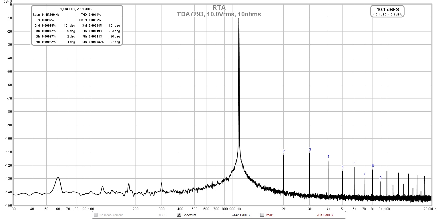
I was able to clean up the measurement setup. The shield on the XLR input cable for the load resistor measurement needed to be grounded to the amp chassis ground. Much cleaner now. Here is measurement for 10vrms into 10ohms (10w):
Here is 20vrms into 10ohms (40w):
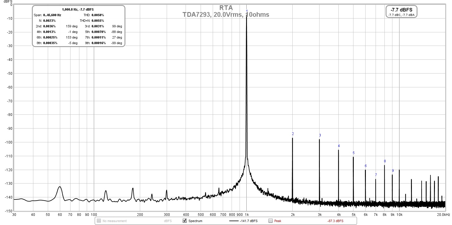
Here is 20vrms into 10ohms (40w):
Attachments
Last edited:
- Home
- Amplifiers
- Chip Amps
- Xmas Amp - Dibya's TDA7293 by Jhofland