For me that's the reason why a round waveguide is really not the best choice for a flat (rectangular) baffle.
I've suspected this for some time. It's reassuring to hear you say it. If one goes freestanding, go round, if in rectangular baffle, go rectangular.
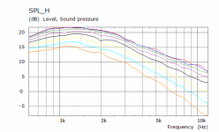
I would be interested especially in the region where the output is falling, typically below 2 kHz or so. I guess I should try that out to see what I get...
Honestly, even down there I would expect an error of less than a dB or so, it's really not a major effect because it's a small load change in comparison with the huge EM damping. But still this is not the region where driver resonances enter the picture and cause several dB errors in the predictions. You could compensate for this is you wanted to, but I don't see the point.
The bigger issue is the plane wave assumption.
For example, the load on a direct radiator changes with frequency. If you model this effect, which I have, you will find a miniscule difference in the results when compared to a model that does not take this load into consideration (like ALL T-S modeling.). It's just not a big effect.
I mean axisymmetric waveguide.
In that case, I miss the point.
It would be definitely great to be able to model the behaviour of a driver in various waveguides just by measuring it in the PWT first.
I've suspected this for some time. It's reassuring to hear you say it. If one goes freestanding, go round, if in rectangular baffle, go rectangular.
If this is the point, then I disagree. Rectangular offers nothing that elliptical doesn't and elliptical doesn't have the issues with the corners.
Well I don't have any evidence at hand, it just seems so logical to me, based on the various results obtained from the sims so far. The abrupt change in curvature really seems to matter. Which is always the case for a round waveguide in a flat baffle.
It would be definitely great to be able to model the behaviour of a driver in various waveguides just by measuring it in the PWT first.
I think that what I am saying is that this is quite possible and certainly better than not using PWT data.
To go further you would need a model of the driver, which I am guessing you are reluctant to do. I did an AES paper on this decades ago, it's not brain surgery.
And, you will need to develop your PWT to measure the wavefront curvature.
With these last two things, you could create a very accurate model of any driver (once measured on the PWT) on any waveguide.
Well I don't have any evidence at hand, it just seems so logical to me, based on the various results obtained from the sims so far. The abrupt change in curvature really seems to matter. Which is always the case for a round waveguide in a flat baffle.
Why "abrupt"? Change in curvature matters a lot, but why must a flat baffle be more "abrupt" than free standing?
Or are we talking about different things again?
Last edited:
Rectangular offers nothing that elliptical doesn't and elliptical doesn't have the issues with the corners.
I think what Mabat is saying, is that any non-rectangular shape in a (ultimately rectangular) baffle will have flat surfaces between the curvature of the waveguide and the roundover of the baffle. Not sure what that would mean acoustically though.
Seems this was cleared up while I was typing 🙂
Last edited:
Quite recently I was actually informed that the brain surgery is not that hard 🙂To go further you would need a model of the driver, which I am guessing you are reluctant to do. I did an AES paper on this decades ago, it's not brain surgery.
But thanks, this is some more food for thought. I'm only not sure it is all worth the effort.
Sure, got that.I think that what I am saying is that this is quite possible and certainly better than not using PWT data.
Last edited:
Yes, exactly. These are two additional places prone to diffraction, in my opinion. You would have to gradually decrease the curvature to zero and then slowly increase it again. This would take a lot of space.I think what Mabat is saying, is that any non-rectangular shape in a (ultimately rectangular) baffle will have flat surfaces between the curvature of the waveguide and the roundover of the baffle.
Are you mixing up "curvature" with "slope"?
The slope has to go to zero, yes. But a smooth blend curve can be created for any size baffle that goes from the design angle to zero - plane of the baffle. The bigger this curve the more gradual, the less the diffraction and reflection, so yes, bigger is better, but "huge" is not required. Sometimes you say things that are more extreme than reality.
Am I mistaken or did Fluid show that the difference between free standing and baffle were not very great?
Didn't Fluid basically show that a rectangular waveguide in a baffle with large roundovers behaves similarly as a free standing rectangular waveguide with rollback termination? That's not the same thing as a round waveguide in a rectangular baffle. It does seem desirable to me to design the shape of the waveguide according to how / where it will be used. I.e. rectangular if it's to end up as part of a baffle and reserve round / elliptical for free standing.
It doesn't seem to me that there is any rational for your opinion. And it's contrary to mine.
I don't have a strong opinion on this at all. But I also don't see why one should not design a waveguide to have the best custom curveature in the corners of the baffle (which effectively makes it rectangular) rather than a standard circular one with these flat surfaces in-between the two curves of the wg and baffle respectively. I don't know whether it would make much of a difference, but are you saying that in your opinion that would actually be detrimental?
No that is not my conclusion, putting a roundover straight on the edge of the horn can be better than using a baffle but if you choose good sizes for the width and depth of the enclosure the overall effect can be similar. The depth of the enclosure can be quite interactive with the width where the waveguide starts to lose control.Even if I interpret fluid correctly that large baffle roundovers have a similar effect as freestanding wg with rollback
This is where the freestanding horn starts to pull ahead again it loses control more gracefully.
Optimizing the curve from start to finish does seem to work better than anything else.
I agree if the baffle is kept minimal it works OK, I tried a variable radius because I liked the look but it did something weird as you moved further off axis. The only thig that changed here from the linked versions above was the edge radius.What people still seem to miss somehow is that this is actually far from being equal. In a baffle you can have the same roundover only at a limited number of points (typically only three), the rest of the circumference just continues with a segment of flat surface, which is not as smooth continuation of the profile... For me that's the reason why a round waveguide is really not the best choice for a flat (rectangular) baffle.
Attachments
with a plane wave tube i can see where i was wrong about length but doesn't the diameter come to bear?
with respect to that i submit this quote from a wikipedia article:
"The duct cross section dimensions are made sufficiently small compared to the wavelength at the frequencies of interest that sound can be assumed to propagate down the duct as a plane wave with no reflections from the sides."
so does that mean that to analyze up to 14KHZ the PWT's cross section or diameter needs to be .968 inches?
No that is not my conclusion, putting a roundover straight on the edge of the horn can be better than using a baffle but if you choose good sizes for the width and depth of the enclosure the overall effect can be similar. The depth of the enclosure can be quite interactive with the width where the waveguide starts to lose control.
Yes, I was imprecise. There was the hidden assumption in my statement that the baffle roundover starts right at the end of the waveguide. And I had not thought about the depth of the enclosure.
- Home
- Loudspeakers
- Multi-Way
- Acoustic Horn Design – The Easy Way (Ath4)