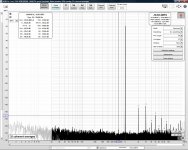
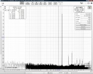
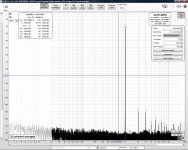
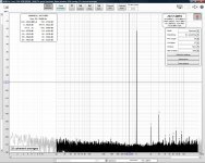
Here is a comparison of more operational amplifier models and brands. These are with my prototype of the "ES9038Q2M No Hump I/V Output Stage" From Post 6944. That is a balanced output I/V stage but I am currently measuring only "half" or the positive output only.
These measurements are made with the lower distortion/noise line-in (1L) on the back of the EMU 1820. The DAC is at -3.0 dBFS because something overloads in the EMU 1820 around -1.0 dBFS.
To deal with repeatability I increased from 32x 128k FFT to 32x 1M FFT. That is much slower but much more repeatable and stable. (Needed to compare small differences.)
Attached in order:
There were a number of surprises:
These measurements are made with the lower distortion/noise line-in (1L) on the back of the EMU 1820. The DAC is at -3.0 dBFS because something overloads in the EMU 1820 around -1.0 dBFS.
To deal with repeatability I increased from 32x 128k FFT to 32x 1M FFT. That is much slower but much more repeatable and stable. (Needed to compare small differences.)
Attached in order:
- JRC4580D
- JRC5532DD (Not as good as Ti due to higher 3rd harmonic)
- Ti NE5532P (First batch, bought from Mouser distributor)
- Ti NE5532P (Second batch, bought from LCSC distributor. This is the best and I will use this batch and model.)
- LM4562NA (Best 2nd harmonic, high 3rd harmonic!)
- JRC4562D (Much higher 2nd harmonic relative to the LM4562NA)
There were a number of surprises:
- Due to the very high 3rd harmonic I judged the LM4562NA to not be the best. (I was expecting it to be the best.)
- The NE5532 was judged to be the best and had unmatched 3rd harmonic performance. Because of this result I found a second batch in my parts bin and the second batch was consistent with the first for lower 3rd harmonic and in fact was even better than the first batch. The first batch is about 19 years older.)
- The Ti and JRC 5532 are not comparable. The Ti has better 3rd harmonic while the JRC has high 3rd harmonic like the other part numbers.
- The Ti and JRC 4562 do not perform the same.
Attachments
-
 Red JRC4580D -3dBFS Line In 1L 1M FFT.jpg217.9 KB · Views: 420
 -
 Red JRC5532DD -3dBFS Line In 1L 1M FFT.jpg217.1 KB · Views: 439
 -
 Red Ti NE5532 -3dBFS Line In 1L 1M FFT.jpg217.5 KB · Views: 405
 -
 Red Second Ti NE5532P Batch LCSC -3dBFS Line In 1L 1M FFT.jpg217.7 KB · Views: 420
 -
 Red Ti LM4562NA -3dBFS Line In 1L 1M FFT.jpg215.5 KB · Views: 425
 -
 Red JRC4562D -3dBFS Line In 1L 1M FFT.jpg217.7 KB · Views: 234
Last edited:
Just FYI: The datasheet is not under NDA. You can get it online at the distributors. Here is the link for Mouser:
https://www.mouser.com/datasheet/2/1082/ES9038Q2M_Datasheet_v1_3-1923484.pdf
https://www.mouser.com/datasheet/2/1082/ES9038Q2M_Datasheet_v1_3-1923484.pdf
I cannot hope you realize the possible consequences of an indiscriminate/blind op amp rolling.
How is the bypassing done on the op-amps on the very best IV stages?
I ask because of the following from Douglas Self (particularly the part in bold):
I am considering an experiment where I move the larger bypass caps to connect directly rail to rail as per Douglas Self (above quote) instead of rail to ground .
But I would like your comments on what is done in the best I/V stages. Any photos of the very best I/V stages (showing the bypassing) would be interesting.
The Douglas Self quote comes from: https://www.eetimes.com/op-amps-in-small-signal-audio-design-part-3-selecting-the-right-op-amp/
I ask because of the following from Douglas Self (particularly the part in bold):
Right now my main bypass for the op-amps is a CBB film 0.47uF straight from pin 4 to pin 8 of the NE5532P. (I have done this for many years and I have forgotten when and why I started doing this.) I do have larger bypass caps from each rail to ground on the proto-boards.The 5532 and 5534 type op-amps require adequate supply decoupling if they are to remain stable, otherwise they appear to be subject to some sort of internal oscillation that degrades linearity without being visible on a normal oscilloscope. The essential requirement is that the positive and negative rails should be decoupled with a 100 nF capacitor between them, at a distance of not more than a few millimeters from the op-amp; normally one such capacitor is fitted per package as close to it as possible.
It is not necessary, and often not desirable, to have two capacitors going to ground; every capacitor between a supply rail and ground carries the risk of injecting rail noise into the ground.
I am considering an experiment where I move the larger bypass caps to connect directly rail to rail as per Douglas Self (above quote) instead of rail to ground .
But I would like your comments on what is done in the best I/V stages. Any photos of the very best I/V stages (showing the bypassing) would be interesting.
The Douglas Self quote comes from: https://www.eetimes.com/op-amps-in-small-signal-audio-design-part-3-selecting-the-right-op-amp/
Pawpaw Version 0.16
Latest Version 1.3
CORRECTION - pawpaw v0.61. Quite a few changes since.
Hi all,
I’m trying to adapt DimDim’s code TFT HiFiDuino Pro Project (hope that’s ok?) to use with
Es9038q2m. I have just started but have a problem with the external Eeprom.
My settings won’t save to the Eeprom.
I have not yet connected Arduino to Dac board, just run it at side for now.
Hooked up sdl/sla to Due at pin 20,21 and Eeprom has build in pullup resistors...
Anyone know if due has internal pullups that interfer with Eeprom?
BR // Daniel

Daniel,
I'm sure its okay 🙂
Duo shouldn't interfere with the Eeprom. An Arduino's pullup resistors have to be enabled in software, even when enabled they are pretty high value around 50k.
If you have the part number for Eeprom then the data sheet should explain how to write to it.
I'm sure its okay 🙂
Duo shouldn't interfere with the Eeprom. An Arduino's pullup resistors have to be enabled in software, even when enabled they are pretty high value around 50k.
If you have the part number for Eeprom then the data sheet should explain how to write to it.
kozard,
The best I/V stages for ES9038Q2M don't use 553x opamps. So, any weird quirks with those don't apply. For I/V stages using OPA1612, I am not aware of any benefit to bypassing from power rail to power rail. To the contrary, I am told that can hurt the sound by folks I trust who have tried it.
The best I/V stages for ES9038Q2M don't use 553x opamps. So, any weird quirks with those don't apply. For I/V stages using OPA1612, I am not aware of any benefit to bypassing from power rail to power rail. To the contrary, I am told that can hurt the sound by folks I trust who have tried it.
Hello,
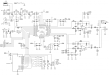
Does anyone have a circuit diagram for this?
Someone posted this as the schematic. (Attached.)
If you just got the board be aware that the output stage needs to be replaced with an I/V stage. I mean it really needs to be replaced.
Attachments
kozard,
The best I/V stages for ES9038Q2M don't use 553x opamps. So, any weird quirks with those don't apply. For I/V stages using OPA1612, I am not aware of any benefit to bypassing from power rail to power rail. To the contrary, I am told that can hurt the sound by folks I trust who have tried it.
Ok. I plan to get OPA1612 in the next order to test. At least in the prototype construction it is easy to change bypass types and locations.
I also don't know if the prototype construction is leading to unusual results. (For example, the NE5532P out performing the LM4562NA.)
That said with NE5532P the I/V stage vastly outperforms the stock voltage stage. I am shocked at the performance with just prototype construction and the humble Ti NE5532P.
If I were to try only one more I/V stage schematic which one would you recommend? The one I have tried so far is the "no THD hump" design one from post 6944.
That schematic may be okay. What may be more important is layout and choice of passive components. All the stuff not shown in a schematic.
That said, if you want you could try the component values suggested in post #3003. They are intended to help preserve waveshape, which may be important for lower frequency transient sounds.
That said, if you want you could try the component values suggested in post #3003. They are intended to help preserve waveshape, which may be important for lower frequency transient sounds.
That schematic may be okay. What may be more important is layout and choice of passive components. All the stuff not shown in a schematic.
Sure. I will get to layout later on. Right now I am doing the best I can with prototype construction.
Once I settle on the schematic and values I plan to get a larger quantity of the specific values of metal film resistors and sort/match them. I am not sure there will be any difference between sorted and matched KOA Speer vs equally sorted and matched Dale? Right now I am using the cheapest eBay assortment 1% metal film with no matching.
For capacitors I assume you recommend Wima FKP2 foil and film? Right now I have Polystyrene in the I/V and Polyester film in the filter. (Simply because that is what I have for those values. But I can not complain about the performance.)
That said, if you want you could try the component values suggested in post #3003. They are intended to help preserve waveshape, which may be important for lower frequency transient sounds.
Ok. I can give that a try. I might duplicate the prototype but using the post #3003 values so that I can try modifying my ES9028Q2M board. That one started out sounding quite a bit better than the stock ES9038Q2M board so I am interested in hearing it with an I/V stage. That one is a USB DAC using AD823 (for the voltage mode output) and Bravo SA9023.
Daniel,
I'm sure its okay 🙂
Duo shouldn't interfere with the Eeprom. An Arduino's pullup resistors have to be enabled in software, even when enabled they are pretty high value around 50k.
If you have the part number for Eeprom then the data sheet should explain how to write to it.
It’s a prebuild 24LC256 with pullups on the small PCB.
It’s possible to find on a Arduino UNO, but with the Due i can’t find it with i2c scanner.
BR// Daniel
It is a silly question but are you running the EEPROM on 3.3V when using it with the Arduino DUE which is 3.3V? I am sure you are but just checking.
The Uno is obviously 5V so the supply and logic levels are a difference between the two.
The Uno is obviously 5V so the supply and logic levels are a difference between the two.
Fancy resistors are Dale RN-6. Some people don't like the other types as much. Will it make much difference at this point? I doubt it. Matching should be useful to help with common mode distortion and noise suppression. However, cheapie ebay resistors may not be as linear as reasonably good quality metal film from a reliable supplier.
At this point you could also use NPO/C0G caps (50v or 100v have better linearity than 25v). That said, Wima FKP2 or FKP4 are quite good caps. Not to start another long running argument, but some experimental evidence even good film caps can take some days in particular operating conditions to fully settle sound-wise. I'll leave it at that.
At this point you could also use NPO/C0G caps (50v or 100v have better linearity than 25v). That said, Wima FKP2 or FKP4 are quite good caps. Not to start another long running argument, but some experimental evidence even good film caps can take some days in particular operating conditions to fully settle sound-wise. I'll leave it at that.
...with the Due i can’t find it with i2c scanner.
Did you reconfigure the I2C library settings to use the correct I2C pins/port for Due?
Fancy resistors are Dale RN-6. Some people don't like the other types as much. Will it make much difference at this point? I doubt it. Matching should be useful to help with common mode distortion and noise suppression. However, cheapie ebay resistors may not be as linear as reasonably good quality metal film from a reliable supplier.
At this point you could also use NPO/C0G caps (50v or 100v have better linearity than 25v). That said, Wima FKP2 or FKP4 are quite good caps. Not to start another long running argument, but some experimental evidence even good film caps can take some days in particular operating conditions to fully settle sound-wise. I'll leave it at that.
I did buy some 1206 NP0/C0G on my previous order. They are 1kV so perhaps I can look at that series. (10pF, 22pF, 100pF. I will see how high they go in value.)
That brings another question. Should I use 1206 NP0/C0G and 1% metal film so that I can avoid putting so many holes in the ground plane? Would that be better? Along the same lines would it be better to surface mount the op-amps? Or would the differences be too small to see?
Sorting and matching the 1206 1% resistors would be a little more challenging but not impossible.
I would surface mount opamps. Some people feel the best of leaded components still sound better than SMD versions, but there are said to be some good little glass cylinder MELF SMD resistor types. For the latter, it might make sense to look at some data sheets. Basically, the very high linearity ones are what I would probably want to try. Also, maybe some other people who have experience with them will chime in.
Regarding holes in PCBs, to my way of thinking a few holes is not a big deal. What is more likely to cause problems are things like ESS warns about, traces cutting across ground planes, things more like that. A short trace duck-under through a ground plane is something I will do if I have to, but I try to do it in a way that will have minimal side effects with ground currents.
Regarding holes in PCBs, to my way of thinking a few holes is not a big deal. What is more likely to cause problems are things like ESS warns about, traces cutting across ground planes, things more like that. A short trace duck-under through a ground plane is something I will do if I have to, but I try to do it in a way that will have minimal side effects with ground currents.
- Home
- Source & Line
- Digital Line Level
- ES9038Q2M Board