One of your positive rectifiers is open ..?
And if that is really no load , 0,170Vp-p is too much ripple. Is one of the regulators staying warm, even with no load? .. one of the regulator-output capacitors? (even lower probability ..)
Uhh .. I'd better wait for Mooly -- this is getting into some pretty low-likelihood failure types / levels.
Cheers
Let me think for a moment...
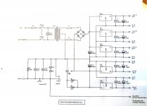
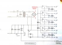
Does your transformer have two separate secondaries (four wires) or does it have a split secondary (3 wires)?
Not sure as it is a pcb mounted toroid. I has 5 pins on the primary side and 4 pins on the secondary.Does that help.What about the circuit diagram. Does that indicate how the transformer would be wired?
Attachments
One of your positive rectifiers is open ..?
And if that is really no load , 0,170Vp-p is too much ripple. Is one of the regulators staying warm, even with no load? .. one of the regulator-output capacitors? (even lower probability ..)
Uhh .. I'd better wait for Mooly -- this is getting into some pretty low-likelihood failure types / levels.
Cheers
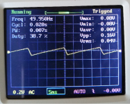
I'm taking the scope off the filter capacitor not after the regulator this time.Do you still think a .17V PP AC ripple is too high? you might be right about the rectifier.I'm guessing that would give 50hz rather than 100hz,effectively a half wave rectifier?
Attachments
That scope picture would be consistent with one open fuse on that secondary.
Jan
Just tested secondary fuses and they are both closed.
You could take a peek at the negative side of the bridge - C12.
My money's on there not being enough sawtooth to see a clean 100Hz.
Something is drawing too much current for a 170mVp-p sawtooth on a 2200uF filter capacitor. -- even given the 20 milliseconds between charging pulses. It should be hard to find a sawtooth on the input of 3 unloaded 7815's.
Cheers
My money's on there not being enough sawtooth to see a clean 100Hz.
Something is drawing too much current for a 170mVp-p sawtooth on a 2200uF filter capacitor. -- even given the 20 milliseconds between charging pulses. It should be hard to find a sawtooth on the input of 3 unloaded 7815's.
Cheers
Not sure as it is a pcb mounted toroid. I has 5 pins on the primary side and 4 pins on the secondary.Does that help.What about the circuit diagram. Does that indicate how the transformer would be wired?
Well I was thinking that if it was a four pin (separate secondaries) that you might have one winding out of phase.
You can test that theory by measuring the AC voltage. On your diagram that is the AC voltage between the two fuses. If it is close to zero then one winding needs its phase reversing.
It looks like the secondaries are wired anti phase to give 50Hz ripple. If you scoped both positive and negative at the same time you will see the ripple is one half wave apart. This is effectively 2 half wave rectifiers rather than a full wave centre tap. And is the reason for the much higher than expected ripple.
Bit of a PCB design error?
Bit of a PCB design error?
You could take a peek at the negative side of the bridge - C12.
My money's on there not being enough sawtooth to see a clean 100Hz.
Something is drawing too much current for a 170mVp-p sawtooth on a 2200uF filter capacitor. -- even given the 20 milliseconds between charging pulses. It should be hard to find a sawtooth on the input of 3 unloaded 7815's.
Cheers
Here is the ripple across C12. What do you think?
Attachments
It looks like the secondaries are wired anti phase to give 50Hz ripple. If you scoped both positive and negative at the same time you will see the ripple is one half wave apart. This is effectively 2 half wave rectifiers rather than a full wave centre tap. And is the reason for the much higher than expected ripple.
Bit of a PCB design error?
If this were so it doesn't explain why the hum was not always there from the start.This system worked fine for over 10 years before the loud hum developed.It is only a recent problem.Could something have developed in the transformer over time to cause a fault.I'm really looking for component failure somewhere rather than design failure unless both have happened and the design failure was never noticed until it caused a further component faliure.
Last edited:
Well I was thinking that if it was a four pin (separate secondaries) that you might have one winding out of phase.
You can test that theory by measuring the AC voltage. On your diagram that is the AC voltage between the two fuses. If it is close to zero then one winding needs its phase reversing.
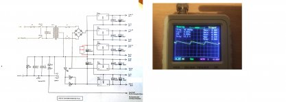
Can I just measure this with my multi meter set to AC volts and should I be measuring as in this diagram(see attachment).I'm assuming being AC it doesn't matter which way round my positive and negative test leads go?
Attachments
Yes, you just measure as in your diagram. Lead polarity does not matter but remember to set the meter to AC volts. If the windings are out of phase you will see virtually no voltage.
Yes, you just measure as in your diagram. Lead polarity does not matter but remember to set the meter to AC volts. If the windings are out of phase you will see virtually no voltage.
I'm getting around 33.8VAC from the secondary windings of the transformer according to my digital multi meter. So I think that means that it is wired into the supply correctly?
The voltage sounds correct, interesting... and so as it doesn't appear to be that you would need two rectifiers in the bridge to be open circuit to do the same thing (create the same 50Hz ripple) which is highly improbable. Just one open circuit would only create 50Hz ripple on one rail, not both.
I think the next thing thing to do is a reality check and prove that the scope is correct in its time-base settings.
I don't know the spec of the scope (its maximum allowable input voltage) and so to play safe I suggest you just touch the probe tip with a finger and you should see lots of 50 Hz stray pickup. It should look like a 'rough' sinewave.
Does it show as 50 Hz and with a 20ms period as you are seeing now? In other words from any point on the waveform to the next similar point should be 20ms apart.
What is an actual load?Here is the ripple across C12. What do you think?
You have to measure all AC and DC (from input to output), otherwise this talk doesn't have much sence. And check all the diodes, fuses, wires, connections etc.Can I just measure this with my multi meter set to AC volts and should I be measuring as in this diagram(see attachment).I'm assuming being AC it doesn't matter which way round my positive and negative test leads go?
Last edited:
The voltage sounds correct, interesting... and so as it doesn't appear to be that you would need two rectifiers in the bridge to be open circuit to do the same thing (create the same 50Hz ripple) which is highly improbable. Just one open circuit would only create 50Hz ripple on one rail, not both.
I think the next thing thing to do is a reality check and prove that the scope is correct in its time-base settings.
I don't know the spec of the scope (its maximum allowable input voltage) and so to play safe I suggest you just touch the probe tip with a finger and you should see lots of 50 Hz stray pickup. It should look like a 'rough' sinewave.
Does it show as 50 Hz and with a 20ms period as you are seeing now? In other words from any point on the waveform to the next similar point should be 20ms apart.
My scope is very basic but I hope it will be adequate for basic audio work.The specs are:
Number of channels:1 Vertical
Analogue Bandwidth:0-200KHz
Sensitivity: 5mV/Div-20V/Div
Sensitivity error: <5%
Resolution:12-bit
Input impedance:1M ohm
maximum Input Voltage:50Vpk
Coupling:AC,DC,GND
Max real time sampling rate:1Msps Horizontal
Timebase:10us/Div-500s/Div
Record length:1024
So should I be touching the probe tip with nothing connected and where does the GND of the scope need to connect to if anything?
Last edited:
What is an actual load?
No load on the power supply at all for this reading across the filter capacitor C12.
Attachments

Last edited:
My scope is very basic ...................
So should I be touching the probe tip with nothing connected and where does the GND of the scope need to connect to if anything?
The ground connection can be floating and not connected to anything. The probe will show voltage picked up by you from all the stray 50Hz fields in a house.
However... your scope would be OK given its 50 volt input rating to measure the secondary voltage and frequency directly. To do this connect the ground of the scope to the power supply ground as normal and then touch the probe onto either secondary fuse.
You should see a sinewave. The frequency will be 50Hz and the voltage will be around 17 volts rms (what your meter would show) but the scope will show the peak to peak voltage which will be around 48 volts from top to bottom. This is the peak to peak voltage.
No load on the power supply at all for this reading across the filter capacitor C12.
The load from just the regulator idle current is enough to show the ripple voltage... normal 🙂
- Home
- Amplifiers
- Power Supplies
- AC Hum from Regulated Power Supply