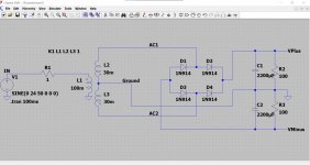
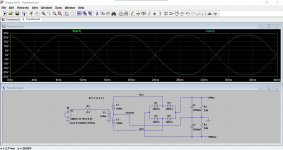
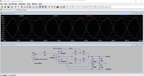
This is a working simulation of a power supply like yours. Look at the four points marked AC1, AC2 VPlus and VMinus. These are shown on the scope traces at the top.
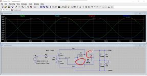
Look at the ripple voltage and the frequency. There is 10 milliseconds between any two similar points. Frequency is 100 Hz.
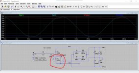
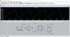
Now look at the two AC voltages. The phase is 180 degrees apart. There is now 20 milliseconds between similar points meaning the frequency is 50 Hz.
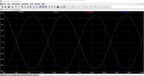
If we put it all together and show all four traces we can see the relationship between them all.
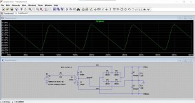
If we reverse the phase of one winding we get 50 Hz ripple and not 100Hz. The two AC traces are still there but now overlay one another. They are now in phase. Image 6.
(your meter reading test shows this isn't happening)
Last image shows what happens with one diode from each half of the bridge open circuit. Now it all behaves as a half wave rectifier and we get 50 Hz ripple again.
Note... the ripple is shown superimposed on the DC voltages and so that is why it looks small.
Look at the ripple voltage and the frequency. There is 10 milliseconds between any two similar points. Frequency is 100 Hz.
Now look at the two AC voltages. The phase is 180 degrees apart. There is now 20 milliseconds between similar points meaning the frequency is 50 Hz.
If we put it all together and show all four traces we can see the relationship between them all.
If we reverse the phase of one winding we get 50 Hz ripple and not 100Hz. The two AC traces are still there but now overlay one another. They are now in phase. Image 6.
(your meter reading test shows this isn't happening)
Last image shows what happens with one diode from each half of the bridge open circuit. Now it all behaves as a half wave rectifier and we get 50 Hz ripple again.
Note... the ripple is shown superimposed on the DC voltages and so that is why it looks small.
Attachments
The ground connection can be floating and not connected to anything. The probe will show voltage picked up by you from all the stray 50Hz fields in a house.
However... your scope would be OK given its 50 volt input rating to measure the secondary voltage and frequency directly. To do this connect the ground of the scope to the power supply ground as normal and then touch the probe onto either secondary fuse.
You should see a sinewave. The frequency will be 50Hz and the voltage will be around 17 volts rms (what your meter would show) but the scope will show the peak to peak voltage which will be around 48 volts from top to bottom. This is the peak to peak voltage.
The load from just the regulator idle current is enough to show the ripple voltage... normal 🙂
Here is the measurement taken at the secondary of the transformer as advised with no load on the output of the power supply.

Last edited:
This is a working simulation of a power supply like yours. Look at the four points marked AC1, AC2 VPlus and VMinus. These are shown on the scope traces at the top.
Look at the ripple voltage and the frequency. There is 10 milliseconds between any two similar points. Frequency is 100 Hz.
Now look at the two AC voltages. The phase is 180 degrees apart. There is now 20 milliseconds between similar points meaning the frequency is 50 Hz.
If we put it all together and show all four traces we can see the relationship between them all.
If we reverse the phase of one winding we get 50 Hz ripple and not 100Hz. The two AC traces are still there but now overlay one another. They are now in phase. Image 6.
(your meter reading test shows this isn't happening)
Last image shows what happens with one diode from each half of the bridge open circuit. Now it all behaves as a half wave rectifier and we get 50 Hz ripple again.
Note... the ripple is shown superimposed on the DC voltages and so that is why it looks small.
So are you saying that either one of the secondaries is reversed or The Bridge rectifier is damaged and that both of these conditions would give the same 50Hz measurement instead of the correct 100 Hz?
Here is the measurement taken at the secondary of the transformer as advised with no load on the output of the power supply.
View attachment 919398
That looks fine. The frequency is correct as displayed and it also calculates out correctly. F=1/T which is 1/ 0.02
It is 0.02 because you have the timebase at 5ms per division and so four squares at 5ms is 20ms in total.
So are you saying that either one of the secondaries is reversed or The Bridge rectifier is damaged and that both of these conditions would give the same 50Hz measurement instead of the correct 100 Hz?
If a secondary were reversed you would actually measure no voltage on a meter if you read between the two AC input pins of the bridge.
And this was the test you did based on your diagram. The two fuses go to the bridge. You could repeat the test with your meter to be sure and this time measure on the bridge itself.
If you did read no voltage it is because the windings are phased incorrectly. The voltage is still there on both, but because both now rise and fall at the same time the difference is zero.
I can't see any other reasons for a 50 Hz ripple from a full wave bridge, either the phase is wrong or the bridge is faulty and that last one is unlikely.
50Hz ripple
Sorry Mooly I misread your reply.So it looks like the Bridge rectifier might be the culprit then?
Thanks very much for the clear explanations with the scope images etc.That's helping me get my head round what should be happening.
Sorry Mooly I misread your reply.So it looks like the Bridge rectifier might be the culprit then?
Thanks very much for the clear explanations with the scope images etc.That's helping me get my head round what should be happening.
Well it would be most unusual for a bridge to be faulty in this way... it just doesn't really happen tbh, plus it would need two of the four diodes to be open circuit and for that to be one diode in each half of the bridge. One diode open would give 50Hz ripple on one rail only, plus or minus depending which side was open. Both to be open... nah.
At the end of the day if no reason can be found then you have to consider it but it is a real outsider.
What I would do is carefully go over all the measurements again. Check that you have the full AC voltage between the AC input pins of the bridge. That will be around 34 volts AC based on your last scope measurement. That is a meter measurement, not scope.
See if this GIF image works. It shows how the bridge converts each half cycle to DC and in doing so how the ripple frequency ends up as twice the AC frequency.
https://i.pinimg.com/originals/c7/4b/fa/c74bfa178ee2ceaf54fc93304fab5e43.gif
https://i.pinimg.com/originals/c7/4b/fa/c74bfa178ee2ceaf54fc93304fab5e43.gif
6L6 once posted a link to a simulator that would demonstrate this and many other funny electron‘s behaviours, where you can change parameters like the animation’s speed and other parameters...
It’s so simple I for one just don‘t get it [emoji848]
Maybe Jim still has the link around?
My2c...
It’s so simple I for one just don‘t get it [emoji848]
Maybe Jim still has the link around?
My2c...
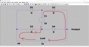
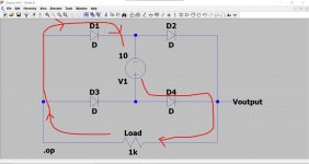
If you struggle to understand how it works then swap the AC supply for a battery and then just follow the current flow around the circuit. Then turn the battery around and follow it again...
Like this. The only difference between these two images is the polarity of the battery.
The current can only flow via D2 in the first image into the load, then from the load it can only flow back to the battery via D3. You have 10 volts on the anode of D2 so it conducts. The load sees 10v less the volt drop of the diode which is about 700 millivolts.
The other end of the load sends its current back to the battery via D3. The anode of D3 is more positive than the cathode and so it to conducts. Again we 'lose' around 700 millivolts across that diode.
So the load see a voltage of 10v less the total 1.4 volts lost across the pair of diodes.
The second image reverses the supply and now the other pair of diodes conducts in exactly the same way.
The circuit converts an alternating polarity of input voltage to one of constant polarity.
Attachments
Well it would be most unusual for a bridge to be faulty in this way... it just doesn't really happen tbh, plus it would need two of the four diodes to be open circuit and for that to be one diode in each half of the bridge. One diode open would give 50Hz ripple on one rail only, plus or minus depending which side was open. Both to be open... nah.
At the end of the day if no reason can be found then you have to consider it but it is a real outsider.
What I would do is carefully go over all the measurements again. Check that you have the full AC voltage between the AC input pins of the bridge. That will be around 34 volts AC based on your last scope measurement. That is a meter measurement, not scope.
Just Measured across the AC inputs to the bridge and got a reading of 33.4V AC with the multimeter so that looks OK.
Checking for a faulty Bridge In circuit
So what would be the best way to check the Bridge Rectifier in Circuit ? Though my Multimeter has a Diode checking feature it uses Resistance rather than voltage drop so don't know what difference that might make measuring in circuit.
So what would be the best way to check the Bridge Rectifier in Circuit ? Though my Multimeter has a Diode checking feature it uses Resistance rather than voltage drop so don't know what difference that might make measuring in circuit.
See if this GIF image works. It shows how the bridge converts each half cycle to DC and in doing so how the ripple frequency ends up as twice the AC frequency.
https://i.pinimg.com/originals/c7/4b/fa/c74bfa178ee2ceaf54fc93304fab5e43.gif
Thanks Mooly. It does indeed work and that certainly does help in explaining how a bridge works.I have often looked at one in a diagram and puzzled over why the current should flow the the way it does even though I understand the principle of forward biasing a single diode-great.
If you check it in circuit (with the power OFF) you should read about 600 to 700 on the diode range when each diode is forward biased.
So with the red meter lead on one of the AC inputs and the black lead on the positive output of the bridge you should read 600 to 700 (which is actually millivolts on the diode range). Transfer the red lead to the other AC input and you should read the same.
Now with the black lead on the AC input and the red lead on the negative output of the bridge you should see 600/700. Transfer the black lead to the other AC input and you read 600 to 700 again.
That is a basic check on all four diodes.
Thanks Mooly. It does indeed work and that certainly does help in explaining how a bridge works.I have often looked at one in a diagram and puzzled over why the current should flow the the way it does even though I understand the principle of forward biasing a single diode-great.
That's good 🙂
One other variation on these scenarios that can cause 50 Hz ripple... but it can't be this if you are measuring on the pins of the bridge itself... would be if one or other of the windings was not connected to the bridge. In effect that is the same as two diodes going open circuit.
Here just D1 and D2 are working with each providing a half wave rectified supply and so with 50Hz ripple. The second winding isn't connected and D3 and D4 are doing nothing.
The second image shows how the complete circuit works. The second winding now tops the caps up every 10ms instead of every 20ms and so you get the 100Hz ripple.
Hope that makes sense. All points are labelled so that you can see how the voltages combine. The two AC voltages in the second image are 180 degrees out of phase (which is correct).
Attachments

If you check it in circuit (with the power OFF) you should read about 600 to 700 on the diode range when each diode is forward biased.
So with the red meter lead on one of the AC inputs and the black lead on the positive output of the bridge you should read 600 to 700 (which is actually millivolts on the diode range). Transfer the red lead to the other AC input and you should read the same.
Now with the black lead on the AC input and the red lead on the negative output of the bridge you should see 600/700. Transfer the black lead to the other AC input and you read 600 to 700 again.
That is a basic check on all four diodes.
With my Multimeter set to Diode(20K) I get the following measurements
1.with the red meter lead on one of the AC inputs and the black lead on the positive output of the bridge I get 6.85KOhms.
2.Transfer the red lead to the other AC input and you should read the same.Yes I also get 6.85KOhms
3.with the black lead on the AC input and the red lead on the negative output of the bridge I get7.43K Ohm
4.Transfer the black lead to the other AC input and I also get 7.43KOhms
What would this mean? As I mentioned my multimeter appears to use resistance rather than voltage drop to check diodes so not sure how this correlates exactly .
Diode range should be a specific range that just gives a number between 0 and say 1.999 (depends on the meter). There should be no units such as ohms or kohms.
You can't relate high resistance readings to the diodes because there will be interactions with other components.
Have a look at this and also have a picture of a diode bridge in front of you. It should make sense then what these readings in the video are are saying. You are really just checking four separate diodes each way around:
How To Test A Bridge Rectifier With A Digital Multimeter DMM - YouTube
Diode range should be a specific range that just gives a number between 0 and say 1.999 (depends on the meter). There should be no units such as ohms or kohms.
You can't relate high resistance readings to the diodes because there will be interactions with other components.
Have a look at this and also have a picture of a diode bridge in front of you. It should make sense then what these readings in the video are are saying. You are really just checking four separate diodes each way around:
How To Test A Bridge Rectifier With A Digital Multimeter DMM - YouTube
OK.I think my meter has 2 functions rolled in to one as it were.The Diode test setting also doubles up as a resistance setting thus my confusion.So within the resistance range there is a 20k position which is also a Diode check function.
Anyhow it looks like from this test if I am performing it correctly I am getting a value when testing the Diodes in forward bias which suggests the Bridge is ok.
So there still seems no answer to why it is producing 50Hz and not 100 Hz.
That's good 🙂
One other variation on these scenarios that can cause 50 Hz ripple... but it can't be this if you are measuring on the pins of the bridge itself... would be if one or other of the windings was not connected to the bridge. In effect that is the same as two diodes going open circuit.
Here just D1 and D2 are working with each providing a half wave rectified supply and so with 50Hz ripple. The second winding isn't connected and D3 and D4 are doing nothing.
The second image shows how the complete circuit works. The second winding now tops the caps up every 10ms instead of every 20ms and so you get the 100Hz ripple.
Hope that makes sense. All points are labelled so that you can see how the voltages combine. The two AC voltages in the second image are 180 degrees out of phase (which is correct).
Just checked continuity from the pins of the secondary all the way to the AC inputs of the bridge and both sides were fine.
- Home
- Amplifiers
- Power Supplies
- AC Hum from Regulated Power Supply