I really don't know what to suggest you try next.
The theory is sound and well known i.e. the ripple component from a full wave rectifier is at twice the AC frequency.
When you look at the ripple you are connecting the scope to the correct power supply zero volt point which is the junction of the two large reservoir caps?
Without having it in front of me it is hard to go further on this. The only thing I can suggest is that you remove the bridge and build it up using four separate diodes and we would fit just two diodes at first to form a half wave rectifier (and 50Hz ripple) and then add the second pair and see if the ripple changes on your scope. It has to 🙂
I really don't know what to suggest you try next.
The theory is sound and well known i.e. the ripple component from a full wave rectifier is at twice the AC frequency.
When you look at the ripple you are connecting the scope to the correct power supply zero volt point which is the junction of the two large reservoir caps?
Without having it in front of me it is hard to go further on this. The only thing I can suggest is that you remove the bridge and build it up using four separate diodes and we would fit just two diodes at first to form a half wave rectifier (and 50Hz ripple) and then add the second pair and see if the ripple changes on your scope. It has to 🙂
Ok.I'll check over what I have done to make sure I'm measuring at the correct point.Out of interest,would it be possible to get a measurement of 50Hz ripple at that point(across the large resevoir cap) if the cap was in some way faulty.When I had the hum problem a few months back I replaced the capacitors with new 50V 2200uF ones and that did solve the problem of the hum but now it has returned.At the time I had no scope so I've no idea what it would have measured.Also it seems odd the capacitors might have failed in such a short time unless they were underrated.50V is Ok isn't it?
Ok.I'll check over what I have done to make sure I'm measuring at the correct point.Out of interest,would it be possible to get a measurement of 50Hz ripple at that point(across the large resevoir cap) if the cap was in some way faulty.
The ripple would always be 100 Hz even if the cap were faulty to the point of being removed altogether. A cap that had lost value would just see the ripple value increase.
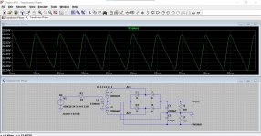
Here we have 2200uF, 220uF and then no cap at all. Look at the voltage scale at the left and how the ripple voltage increases for each reduction in capacitance. With no cap present the voltage dips all the way to zero volts.
Note the frequency stays the same, always 10 millisecond (so 100Hz) between any two points on the waveform.
Attachments


Rectified voltage under load can possibly be too low for IC regulators.
Yes, and that voltage has to include any dips caused by ripple. The big mystery here is why the ripple is at 50Hz and not 100Hz.
Loose fuse clip? Have seen one that wasn't tight enough, yet every time it was tested, measured OK -- because some otherwise halfway competent tech (am I the only one? 😱) wedged the point of the test probe between the metal end-cap of the fuse and the arm of the clip, reinforcing the connection .. 😡
Cheers
Cheers
Last edited:
Loose fuse clip? Have seen one that wasn't tight enough, yet every time it was tested, measured OK -- because some otherwise halfway competent tech (am I the only one? 😱) wedged the point of the test probe between the metal end-cap of the fuse and the arm of the clip, reinforcing the connection .. 😡
Cheers
Thanks but I checked around the fuses by touching the solder pins and pcb track.Interesting situation though!
Just to finally come back to a basic description. If these conditions are met then the ripple has to be at 100Hz. Rick has given me an idea 🙂
1/ The scope ground lead must connect to the line marked in the diagram. That line should have continuity (zero ohms) to all the points it is actually supposed to go to such as the junction of the big caps.
2/ The scope shows the 50Hz secondary voltage on each of the two points that were marked 'here' on the diagram.
3/ That the secondaries are phased correctly.
If those conditions are met and the bridge is good then the ripple can not be anything other than 100 Hz.
Another idea as a test...
1/ Look at the ripple again and confirm you still see the incorrect 50Hz displayed.
2/ Switch OFF and now remove just one fuse.
3/ Retest. Has anything changed? Look at the ripple on both rails. Is it all identical or is it different with one fuse missing.
4/ Switch OFF. Replace the missing fuse and now repeat the test this time with the other fuse missing.
Attachments

Faulty Rectifier to blame
I've just replaced the bridge rectifier in the power supply and that seems to have done the trick. The replaced rectifier measured correctly at 100Hz when the old one measured at 50Hz.The horrrible mains hum has gone and I can now enjoy my music once again.
Thanks to everyone for their help and advice. I learnt a lot while trouble shooting this fault.
 it really is very unusual to have a rectifier fail open circuit.
- Home
- Amplifiers
- Power Supplies
- AC Hum from Regulated Power Supply