My best advice to you is to ignore at least half of what's been posted. The computer "models" are especially impenetrable.
And, yes, you can. All good fortune,
Chris
And, yes, you can. All good fortune,
Chris
RC time constant calculator | MustCalculateCan I try to put the 0.1u + 0.1u in series for a total of 0.05uF in place to 0.1u in the coupling caps? Just for test the result.
I think you also want to know the expected result of the test.
There is a sch showing the actual voltages here: Rate/critique my Dynaco A410 mods..
My spice model gives same voltages, provide all the sources data are available, is a tool to check against another work.
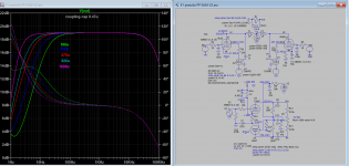
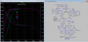
Hi, I've tried the 0.05uF.
I observe a shift in frequency higher about 3/5 Hz (by eye), with the same amplitude. Seems to agree with the simulation at post # 37
I observe a shift in frequency higher about 3/5 Hz (by eye), with the same amplitude. Seems to agree with the simulation at post # 37
Do you have the .001uf FB cap and the 1K resistor both as in the schematic? The FB cap is designed to customize the FB phase shift for the original transformer. You have a different OPT so the .001 cap will not give the same results. You can lift that off to test but you will need a scope to actually find the best cap for the Hammond tranny. By the way, the original Dynaco OPT has a different UL screen tap percent of @23% as opposed to the Hammond @40% tap, so you really have a different amp and different FB requirements and the 1K resistor may need to be optimized, also.
No I don't have tried this, only tried to increase the input cathode cap but no success.Have you tried increasing the cathode output caps?
I also disconnected the virtual gnd of 6.3v from the GND Star.
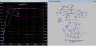
Last try I replaced 0.1u with 0.42u (0.1//0.1//0.22) an the result it's very fine, the cone it's absolutely freeze.
So in summary, the decrease of 0.1u caps aren't effect. In fact it shifts the resonance a few hz forward but with the same amplitude.
The increasing, instead it has good effect specially with 0.42uF. Seems to agree with the simulation at post #37.
I forgot to tell you that it sounds very good with a bass I didn't expect from 10W and very natural voices. I am very happy with this result🙂
I should do the last test with increasing the cathode output caps? What value?
From the simulation at the post 29, the 200uF looks good.
Do you have the .001uf FB cap and the 1K resistor both as in the schematic? The FB cap is designed to customize the FB phase shift for the original transformer. You have a different OPT so the .001 cap will not give the same results. You can lift that off to test but you will need a scope to actually find the best cap for the Hammond tranny. By the way, the original Dynaco OPT has a different UL screen tap percent of @23% as opposed to the Hammond @40% tap, so you really have a different amp and different FB requirements and the 1K resistor may need to be optimized, also.
Yes I know but unfortunately I don't have an oscilloscope.
As you can see it has already been done
DIY Push-Pull (PP) 6V6 / 6V6GT Tube Amplifier Schematic
With the 6V6. in fact the scheme foresees both El84 and 6V6
I preferred the El84 because it is very musical and refined.
Last edited by a moderator:
No I don't know.
That is most essential to know when GNFB is used. Assume that you have excessive amount of GNFB (15 dB...) and like now, stability problems exist.
What ever you do with capacitors here and there, the main reason remains.
If you use moderate amount of GNFB (9...13 dB), you never experience this kind of prolems. So, find first out the amount of GNFB.
GNFB up to 20 dB can be used if design is made properly with high class OPT.
I suggest 200uF or bigger whatever you have to hand. I only suggest it as its what the simulation suggests is a fix - and I find its best to go with the science. You have a much better output transformer at the bass end but its also the source of your wows. Normally its the HF that goes unstable - so your lucky.
Last edited:
Last try I replaced 0.1u with 0.42u (0.1//0.1//0.22) an the result it's very fine, the cone it's absolutely freeze.
So in summary, the decrease of 0.1u caps aren't effect. In fact it shifts the resonance a few hz forward but with the same amplitude.
The increasing, instead it has good effect specially with 0.42uF. Seems to agree with the simulation at post #37.
I forgot to tell you that it sounds very good with a bass I didn't expect from 10W and very natural voices. I am very happy with this result.
While this may make you happy, you didn't actually fix the problem. This is the same as running your car heater with the windows down to keep the motor from overheating. Are you going to leave the higher value cap in place when you build the final version on a real chassis?
I've tried 270uF Nichicon MUSE but nothing effect, on the contrary, he added a little buzz that previously absolutely absent.I suggest 200uF or bigger whatever you have to hand.
The bottom end response can only be extended when cathode cap and coupling cap are increased at the same time. Since you have now 0.47u coupling cap in circuit, with 200u the bottom end response at 50Hz is increased by at least1.5db hence your hear the buzz (50/60Hz) or hum. In doing so the sim shows that the phase shift is much reduced which is a good thing if the oscillation is due to the phase shift of para-phase inverter. As the oscillation is about 1Hz, so if I set the sim stop frequency to 2 Hz, all values cap gives zero phase shift. And if I use another phase inverter, no such phase shifts occur. So that is something about paraphrase inverter it is known to have greater phase shift at the freq extreme.
So it's phase shift at 1 Hz that matter, and coupling is coming from OT, so how OT passed 1 Hz (even at very low level, possible? or due capacitance coupling?).
PS: I disable Nfb, the phase shifts still present.
So it's phase shift at 1 Hz that matter, and coupling is coming from OT, so how OT passed 1 Hz (even at very low level, possible? or due capacitance coupling?).
PS: I disable Nfb, the phase shifts still present.
Attachments
Last edited:
At the risk of going down another blind path stick with the .47uF if it works for you. If the cone is frozen that good enough for you. I not sure I can give you a complete fix without sicking the whole thing on LTspice and looking for myself. Enjoy the improved bass.
I despair of this subset of discussions, those with completely understandable, common-logic, no-math-above-ordinary-algebra, solutions, which are still approached as if a deep mystery.
Bode plots are sometimes considered some deep Heaviside voodoo, but are really just stick-figure log-log frequency and phase response. That's it. There is no more. It's something that everyone can understand intuitively, even me (not the sharpest pencil in the pocket protector).
A good way to start, for those interested in a working model, is to learn about op-amps. And don't snicker that you're too pure a soul - the first op-amps were made with octal based valves. But the concept, the model, that you can develop is powerful enough to understand even complicated signal paths like a vacuum valve amplifier with loop feedback.
I'll only add that the converse is also true. If unwilling to learn to model a feedback amplifier, the OP is left with anecdotal, often conflicting, patches from well meaning but uninformed (the OP in these situations don't have the capability to measure, by definition) folks, and usually the OP finds some quasi-stable fix, decides he has a life, and moves on.
Does that come across as harsh? Because it's not intended to be any more, or anything less, than an activist call to bootstrap our DIY level of understanding into the 1960's.
Your Obedient Servant,
Chris
Op is trying to duplicate an amp from a well known amp maker, but got some negative results. OP will ususally indicate whatever skill level he has, so don't blame him when he doesn't know what NFB level is in use and so on. You should know better.
I don't blame the OP; quite the opposite. He (it's almost always a "he" on DIYaudio) is somewhere on the learning curve, has minimal instrumentation, and has not yet developed a working mental model. This is how we all are when approaching a new interest - it's the learning part that keeps us interested.
I'd actually disagree that he got negative results, in a certain perspective. The observed fact that the output transformer's primary inductance is so critical has become a source for a deeper understanding of the machine he's making, and potentially empowering for all future projects.
I guess my bitch is that we see this same problem on diyAudio so often, but never seem to actually solve it. It's a problem that's completely understandable and fixable, but we leave it unfixed. I blame those who know better, but don't manage to convey their information usefully. Includes me, of course.
YOS,
Chris
Chris is not blaming the builder here. He is pointing out quite correctly that there is a lack of understanding of feedback loops amongst some offering advise. The result is a rather confused set of answers which does not help the designer. However that's a forum for you and there is little I think that can be done. However I do think it does help if people do stick to the science. I have to say in this case I would have to put the simulation on LTspice with an accurate transformer model in order to resolve this properly.
- Home
- Amplifiers
- Tubes / Valves
- PP EL84 Problem (HELP)