The zener has been changed to 2V to give 7V on the heaters. Only Philips valves are 7.6V, my bad for the original spec.
The secondary for the heaters should be rated at 1A.
Patrick what voltage do you have on the 3300uF C3P?
Alan, I've just realised there isn't a C3P. The reading I gave was C1P, which is the 3300uF 25v cap. Am I right in assuming that was a typo?
Flikoman, with the 7805 out voltage across C1P is under a volt. It's .85v atm and slowly creeping up, but I suspect not much further.
Very strange ... Disconnect HV secondaries from PCB and replace D1P and D2P, try only LV for now.
Am I right in thinking that the fault can only be between the LV input, which is ok, and the voltage regulator.
Which is D1P, D2P C1P, the 2v zener and R1P (very appropriate). Is there anything else.
Also, are there any particular specs for the 2v zener, as there's no Mouser or Farnell reference in the BOM. It's certainly a 2v .5w that I'm using, but should there be anything special about it.
Which is D1P, D2P C1P, the 2v zener and R1P (very appropriate). Is there anything else.
Also, are there any particular specs for the 2v zener, as there's no Mouser or Farnell reference in the BOM. It's certainly a 2v .5w that I'm using, but should there be anything special about it.
Am I right in thinking that the fault can only be between the LV input, which is ok, and the voltage regulator.
Which is D1P, D2P C1P, the 2v zener and R1P (very appropriate). Is there anything else.
Also, are there any particular specs for the 2v zener, as there's no Mouser or Farnell reference in the BOM. It's certainly a 2v .5w that I'm using, but should there be anything special about it.
With regulator desoldered, zener diode and resistor should not make any difference. You can lift one side of resistor just to be sure. If I remember correctly, resistor is on Vout side of regulator. Not sure 100%.
4007 is 1000v, 4002, 100v.
That will work ok?
Yes, no problem.
Last edited:
Done that, voltage over C1P still the same.
Starts around half a volt, then creeps up to about 1.2.
Starts around half a volt, then creeps up to about 1.2.
You sure you connected the secondaries the right way to PCB?
This should be very simple and straight forward. Maybe cold joint on C1P?
This should be very simple and straight forward. Maybe cold joint on C1P?
Sorry my eyesight, it is C1P.
Do you have the centre tap of the secondary winding connected?
Ah another thought. Are you using a transformer with two 10V windings?
If so reverse just one of them.
Do you have the centre tap of the secondary winding connected?
Ah another thought. Are you using a transformer with two 10V windings?
If so reverse just one of them.
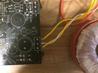
It's a toroid from Tiger toroids.
secondary winding is two yellows and a white. Two yellows in the LV outer terminals, white in centre tap.
AC reading across yellow and white (both sides) is 10.5v, across the two yellows is 21v.
secondary winding is two yellows and a white. Two yellows in the LV outer terminals, white in centre tap.
AC reading across yellow and white (both sides) is 10.5v, across the two yellows is 21v.
Did you check rectifier diodes? Or even replaced them?
D1P & D2P? I've both checked and changed them.
I've reflowed everything in that area to make sure, although nothing looked dry. No difference.
Thanks for your help guys, this is giving me a headache. I've ordered some more 3300 caps, which I'll try. Mainly because that's all that's left.
- Home
- Source & Line
- Analogue Source
- Bigbottle Phonostage Builders thread