No problem 🙂
Now you say 'that the ripple was a lot higher under load'. Do you mean it went higher than 10 millivolts when under the load of the preamp?
I'm just wondering if you have a ground loop with the test equipment (the scope) if the ripple is present on all the outputs.
This might sound crazy but can you see any ripple if you scope the ground lines of the regulated supplies. If you can then you have a measurement artefact for this 10 millivolts.
No. The 10 millivolt ripple was measured at the output of the regulators under load-ie- connected to the pre-amp. When I first measured the output from the regulators not under load-ie nothing connected to the power supply, there was no noticeable ripple.The ripple only went up to 10 millivolt when the power supply was connected to the Pre-Amp.
OK, so 10 millivolts is certainly higher than would be expected from a reg and yet on the other hand it would be consistent with a measurement anomaly... ground loop caused by the scope etc. That can be hard to eliminate.
If the voltage across the reservoir caps (including ripple... this is VERY important) is always above the regulators drop out voltage and if all the regulated outputs are showing this 10mv then I think you have to look elsewhere.
If the ripple voltage on the reservoir caps dips below the regulators drop out voltage then a brief ripple spike would appear on the regulated output.
Have you tried powering up the amp and preamp with nothing else apart from speakers being connected? Is it possible you have added a new source component that has created some loop somewhere?
Mooly, the ripple is not consistent at the regulator output when under load.It goes through a 3 second or so cycle where it ramps up to the 10 millivolts ripple and then falls down to almost nothing and then goes back up.
What did you mean by looking elsewhere in your second paragraph?
Thanks
What did you mean by looking elsewhere in your second paragraph?
Thanks
I meant looking somewhere else other than the power supply itself.
Ramping up and down is strange. Does the perceived level of hum follow this ramping up and down or is the hum at a constant level?
Things like this can be difficult to diagnose at a distance unfortunately 🙁
Ramping up and down is strange. Does the perceived level of hum follow this ramping up and down or is the hum at a constant level?
Things like this can be difficult to diagnose at a distance unfortunately 🙁
I meant looking somewhere else other than the power supply itself.
Ramping up and down is strange. Does the perceived level of hum follow this ramping up and down or is the hum at a constant level?
Things like this can be difficult to diagnose at a distance unfortunately 🙁
The level of Hum coming out of the speakers seems to be constant and is unaffected by the volume control so doesn't seem to be on the signal.
OK, so I think what I would do now is to first of fit shorting plugs to the power amp inputs and run that in isolation and make sure it is hum free. The shorting plugs are essential, not just to remove anything from the input but also to tie the input to the signal ground.
If that is OK then connect just the ground connection of the preamps signal output to the ground of the power amps input sockets. Leave the shorting plugs in place.
If the hum reappears you have a loop somewhere.
Also... and this is worth doing first perhaps. Look at the output of the preamp with the scope. Have just the preamp powered up and nothing else connected to it.
If you see hum then do as I mentioned earlier and probe the output ground of the preamp with the scope. You should see zero hum and noise of course. Anything else and you have a measurement loop somewhere that is adding to the confusion.
Just discovered that the Hum is only high with the Power Amp connected to the high output from the Pre-amp.If I connect the Line level output to the Power Amp the hum is very low.The High Output from the pre-amp comes from a class a headphone circuit integral to the Pre-Amp. I like to use this as I don't get full volume from the line level output due to it's low sensitivity.It only outputs about 500mV and my power amp needs 1V for full output.
Would there be any point in fitting a dummy load to the output of the power supply and see how that affects the ripple from the regulator outputs.If this is a good idea what resistor and power rating would I need and what would be the set-up?
An additional load is a great idea 
You could load each supply individually in turn and you only need dab a resistor across each rail quickly for a couple of seconds and see if the hum alters.
If you used a 47 ohm then that would pull around 300 milliamps. Wattage would need to be 5 watt for sustained operation but if you have Teflon fingers then a cheap 2 watt carbon or metal film would be OK for a few seconds use each time. You would just dab it in turn across each of the 100uF caps on the output of the regs.
The bit about the different line level outputs suggests a fundamental problem with the preamp. If the line level has very low hum and assuming the headphone amp input is that line level feed then then the headphone amp would increase that hum by whatever gain factor the headphone stage has.
One test would be to short the headphone amp inputs and see if the hum falls to zero.
Is it all diy preamp and power amp or are they commercial units?
An additional load is a great idea
You could load each supply individually in turn and you only need dab a resistor across each rail quickly for a couple of seconds and see if the hum alters.
If you used a 47 ohm then that would pull around 300 milliamps. Wattage would need to be 5 watt for sustained operation but if you have Teflon fingers then a cheap 2 watt carbon or metal film would be OK for a few seconds use each time. You would just dab it in turn across each of the 100uF caps on the output of the regs.
The bit about the different line level outputs suggests a fundamental problem with the preamp. If the line level has very low hum and assuming the headphone amp input is that line level feed then then the headphone amp would increase that hum by whatever gain factor the headphone stage has.
One test would be to short the headphone amp inputs and see if the hum falls to zero.
Is it all diy preamp and power amp or are they commercial units?
Ah, I was thinking more of a bench test,not connected to the pre-amp but to use a dummy load to see if the regulation breaks down and the ripple rises in the same way that produces the hum with the pre-amp.
Most of my set up is home made.
I have a power amp using the Doug Self class B design, the pre-amp is a John Linsley Hood design in Kit form from Hart and the speakers are an IPL Kit.
Just discovered that the Hum is only high with the Power Amp connected to the high output
from the Pre-amp.If I connect the Line level output to the Power Amp the hum is very low.
Can you post the schematic of the power supply and headphone amplifier circuit?
Does the headphone amp run off the 3 pin regulators, or the unregulated input voltage?
A low frequency beating with the hum may be an instability in the circuit, and could vary with loading.
Last edited:
The headphone runs off one of the regulated supplies.Can you post the schematic of the power supply and headphone amplifier circuit?
Does the headphone amp run off the 3 pin regulators, or the unregulated input voltage?
A low frequency beating with the hum may be an instability in the circuit, and could vary with loading.
Attachments

One thing worth checking is whether the DC voltage at the output of that headphone amp stage is at 0.00 volts DC.
If your power amp stage that you feed from this is also DC coupled then you could have a problem... the DC would be amplified. Lots of scenarios for that situation and possible hum... just measure it.
If your power amp stage that you feed from this is also DC coupled then you could have a problem... the DC would be amplified. Lots of scenarios for that situation and possible hum... just measure it.
Correct Measuring Point?
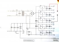
I've been taking my scope measurements from the positive and earth points as in the attached diagram. Is this correct and should the ripple measured from here be 50HZ or 100HZ.I'm thinking this is a split rail design and therefore not sure how that effects the frequency of the ripple?
Thanks
I've been taking my scope measurements from the positive and earth points as in the attached diagram. Is this correct and should the ripple measured from here be 50HZ or 100HZ.I'm thinking this is a split rail design and therefore not sure how that effects the frequency of the ripple?
Thanks
Attachments
Something Else occurred to me.I had a channel intermittently drop out on me and that turned out to be a dirty Jack socket on the headphone amplifier cutting out the feed to the high output pre-amp. Could something similar be happening to the earth on the jack sockets.It is after all only affecting the high output coming from the head phone amplifier.
If that were to be the case how would I test that?
If that were to be the case how would I test that?
The ripple is at 100Hz because of the full wave rectification but should be so low as to be pretty much non measurable at the regulator outputs.
You will see the full ripple voltage at the input to the regulators (across the 2200uF caps) and that will be noticeable. The minimum dips in the ripple must always remain above the regulators drop out voltage... so about 17.5 volts as a minimum. Ideally there should be a bit more headroom than that.
You will see the full ripple voltage at the input to the regulators (across the 2200uF caps) and that will be noticeable. The minimum dips in the ripple must always remain above the regulators drop out voltage... so about 17.5 volts as a minimum. Ideally there should be a bit more headroom than that.
But it seems to me it is power supply noise sensitive, so power lines have to be very clean.The headphone runs off one of the regulated supplies.
Maybe there is some small mistake on power supply lines, so IC regulators don't do their job well?
Last edited:
scope measurements of power supply
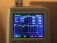
I've just measured the power supply unconnected and with no load.This is what I get between earth and the positive side of C11. Seems odd that the Frequency is 50Hz at this point from a full wave rectified output or is this down to where I'm taking the measurement from?
I've just measured the power supply unconnected and with no load.This is what I get between earth and the positive side of C11. Seems odd that the Frequency is 50Hz at this point from a full wave rectified output or is this down to where I'm taking the measurement from?
Attachments
- Home
- Amplifiers
- Power Supplies
- AC Hum from Regulated Power Supply