Looks like standard 3d printing pattern.
Here is one. Maybe not as pretty but the pattern is the same.
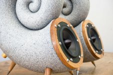
Nautilus speaker by bberkel - Thingiverse
Natually, the printing pattern is similar, though the material is completely different.
To me, this material also 'looks' very suitable. Perhaps it's the same as shown before, but a different color.
Attachments
Natually, the printing pattern is similar, though the material is completely different.
To me, this material also 'looks' very suitable. Perhaps it's the same as shown before, but a different color.
That just looks like rustoleum stone paint...
American Accents(R) Decorative Finishes Stone Spray Paint Product Page

It seems from the results gathered so far that the actual contribution of HOMs (inherent to a profile) will be generally very low, at least up to a rather high frequency. I'm more and more convinced that what is observed as "disruption of pressure field" is almost always caused by a suboptimal mouth termination. Take any shape of the Salmon horn family and make a smooth termination e.g. via a clothoid and I'm sure it will all behave virtually the same. That's the reason I said it is "nothing more" than a smoothly terminated exponential horn. Because in my view there's really nothing more to it. I still may be missing something, but then show me.The intention, purpose if you wish, of JMLC's method is to calculate/design horns that provide the smallest reflectance and diffraction, a smooth pressure field and subsequently (due to the 'natural' expansion) generate a very low amount of HOMs.
"When calculating a Le Cléac'h horn, there is nothing special in my spreadsheets or software related to the curvature of the mouth. The curved back mouth is not intended nor provoked, it is the result of the "design by nature" of the horn."
No stone sprays, please 🙂
Last edited:
So, what was the intention? 🙂
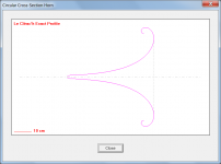
The intention was to be able to generate a horn profile given a defined isophase wavefront area expansion rate. Jean-Michel assumed a hyperbolic-exponential expansion, but it could just as easily been have something else (eg. conical, exponential, parabolic). It was a brilliant piece of work, freely shared, and arguably one of the very few genuine advances in acoustical horn design in the last fifty years.
Attachments
what's the merit?
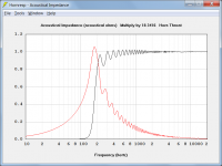
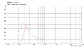
For one thing, a superior horn throat acoustical impedance characteristic loading the driver, due to the controlled expansion rate and the better impedance matching at the horn mouth resulting from the rollover inherent in the Le Cléac'h generated profile.
Attachments
When I asked about the intention, I of course was interested in this claim: "... but they clearly work as intended." Clearly I would like to understand what was the intention and what was verified. The smoothness of the polars? Is that it?
Frankly, I see absolutely nothing special about the acoustical impedace you show. Somewhat suboptimal, at best.
Frankly, I see absolutely nothing special about the acoustical impedace you show. Somewhat suboptimal, at best.
Last edited:
Frankly, I see absolutely nothing special about the acoustical impedace you show. Somewhat suboptimal, at best.
I bow to your superior knowledge in such matters.
Years ago I was a dealer in Auto-Tech horns. I have implemented all kinds of horns in my client systems. I can agree that JMLC horns have a very good phase curve, but express the beaming effect in the upper range. The stage effect is so strong that it sounds in your head. But it is impossible to listen for a long time, it is tiring. When I first tried SEOS waveguides, I was amazed at how tireless it sounds. The stage was no longer in my head, but in front of my eyes and the sound had become wider. Currently i am listening ATH calculated round waveguide and i can say it is the best performance.
Last edited:
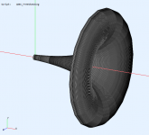
I decided to release my first "serious" design of this type... ST260 (ST = Small Teaser), cca ⌀260 mm x 83 mm. Throat entry angle is 19° and should work well with majority of 1" drivers.
Thank you for this! It should make a great reference horn. 😀
It seems from the results gathered so far that the actual contribution of HOMs (inherent to a profile) will be generally very low, at least up to a rather high frequency. I'm more and more convinced that what is observed as "disruption of pressure field" is almost always caused by a suboptimal mouth termination.
To my, albeit limited, knowledge, HOMs are (mainly) related to higher frequencies and as such a byproduct of sudden changes in the horn profile near the throat.
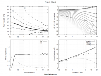
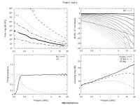
Here's the whole beauty from the previous example (numerical issues above 8 kHz due to the reduced mesh resolution). And now give me a break with this beaming ****.
Not my cup of tea, but I bet this horn works wonderfully with the TAD TD-2001.

The intention, purpose if you wish, of JMLC's method is to calculate/design horns that provide the smallest reflectance and diffraction, a smooth pressure field and subsequently (due to the 'natural' expansion) generate a very low amount of HOMs.
Well, as this thread shows, none of that happened.
- Home
- Loudspeakers
- Multi-Way
- Acoustic Horn Design – The Easy Way (Ath4)