Yes. Caps have sound «signature». For the occasional listener, it's not apparent. but for a trained ear, with good system, especially on decent headphones, you can ear the difference. that said, more often that not, it does not have a big impact and it is the last thing i tweak generally. I like use COG NPO in feedback of audio signal, over film.
I guess it may vary on the circuit topology.
If I take the 2 very last projects of acceptable quality I had to tackle around this topic, namely the B1 Korg and the Aiyima 04 amp, I found the following TO MY EARS:
- B1 Korg, perhaps because Papa did already the job, PS cap tuning brought very little. However, playing with PPP caps in the signal path brought a lot
- Aiyima, well admittely not as transparent, but playing with bypass caps and even supressing some of the numerous signal path caps brought surprisingly very little, whereas adding bypass caps to the OPAs PS did unexpeted miracles. It was though supposed to be"by the book" initialy... in fact a copy of TI's eval board mainly in that regard, and acceptable track length also by TI's excellent tech sheet.
OK, one is a tube pre, the other a Class D amp, but at the end in a few decades I must say I am always suprised to see how things that are usualy quite reccurent may not affect (or affect far more than anticipated) some units. It seems more to have to do with the topology and hence sensitivity or PSSR abilty etc.
Important though is: it is worth trying, or addressing if designing your own PS, which I am doing for a majour power amp so I better put all my chances on my side while also avoiding silly resonnances overdoing it blindly with bypass caps... 'nother topic however, will post under FSSA-2 when the time is right.
Claude
Go figure...
Hearing the difference between X7R and film or C0G bypass caps?
Well I can.
But more importantly, Gilles can, my wife can, my mother can, my son can
May I assume Gilles is your dog?

syn08,
placing a resistor to ground increases biasing. i think it is the intended purpose.
increasing bias increases linearity and transconductance. which is desirable, even for amplifier output stages, but increases heat.
placing a resistor to ground increases biasing. i think it is the intended purpose.
increasing bias increases linearity and transconductance. which is desirable, even for amplifier output stages, but increases heat.
placing a resistor to ground increases biasing
No it does not.
Too many cooks isn't even close.
Having had a small taste of this thread, do you really think it is possible to distil it all down to a board all can be happy with ? Just choosing the dac manufacturer, not to mention chip, should see post count hit 5 figures.
Can't you guys design a DAC from scratch? With any chip AK or ESS or any other DAC chip. I mean a PCB design, and then people can put components on it. I think improving an existing DAC would be difficult than designing a new one, isn't it?
Having had a small taste of this thread, do you really think it is possible to distil it all down to a board all can be happy with ? Just choosing the dac manufacturer, not to mention chip, should see post count hit 5 figures.
"May I assume Gilles is your dog"
Yes mate, you can.
Note others probably wouldn't, and they would be right, but that assumption of yours is about as relevant as the rest of your comments, so you would remain quite consistent
Back to topic... 20y ago some older OPAs, such as my long time favourite AD825 for output stages, benefited quite from Class A bias. No clue to what it was due, but sound could be adjusted and sounded better to my ears with a couple of mA. Instead of a resistor I used transistors for consistency, back then available non expensive 2SK170.... heresy! and say that it still forms the output stage of my DAC since. Last year I got a batch of OPA1656 for testing and in various audio set ups (gains, impedance etc.) from RIAA amp to HP amp it performed very well when used for its application field, beating to my ears all I used. It didn't benefit though from Class A biasing, nor did other OPAs I played with then (ADA4625, ADA4627, LTs, TIs...).
There is thread on OPA1656 and the person in charge of its design elaborated why additional Class A biasing shouldn't bring the expected benefits - in fact it has the equivalent of some bias already 'dialed in' for good performances. That thread is on DIYA.
Claude
Last edited:
^^^
Focus ClaudeG, and please stay on topic. May I remind you the two points under discussion:
A) The audibility of film caps vs. X7R caps used as op amp power supply bypass. To this topic, you contributed with the important information that yourself, your family and your dog can hear the difference. Good for you, there’s nothing else to add here.
B) Adding an extra load to a regulator output is an “old trick” that provides "a step improvement in sound quality“. To this, you quoted the “trick” of loading an op amp output with a current source, which is (or should be) obvious for everybody, including your dog, a different story. The op amp output loading may have, in certain cases (but not always!), the positive effect of lowering the open loop distortion of the op amp class AB output stage, by displacing the upper half Gm, so that the Gm doubling distortion mechanism contribution is lowered. Your dog would of course note that there is no class AB stage at a DC regulator output and even if an op amp would be used at the DC regulator output, the distortion of such a DC regulator op amp output is completely irrelevant.
May I assume Gilles is your dog?
Just assume Gilles is reading your comments... Stay correct.
Gilles.
Last edited:
Back to topic... 20y ago some older OPAs, such as my long time favourite AD825 for output stages, benefited quite from Class A bias. No clue to what it was due, but sound could be adjusted and sounded better to my ears with a couple of mA. Instead of a resistor I used transistors for consistency, back then available non expensive 2SK170.... heresy! and say that it still forms the output stage of my DAC since. Last year I got a batch of OPA1656 for testing and in various audio set ups (gains, impedance etc.) from RIAA amp to HP amp it performed very well when used for its application field, beating to my ears all I used. It didn't benefit though from Class A biasing, nor did other OPAs I played with then (ADA4625, ADA4627, LTs, TIs...).
There is thread on OPA1656 and the person in charge of its design elaborated why additional Class A biasing shouldn't bring the expected benefits - in fact it has the equivalent of some bias already 'dialed in' for good performances. That thread is on DIYA.
Claude
Claude, we used to do same class A biasing with opamps like OPA627.
I believe with the 1656, the rail to rail OP architecture comes with a design
side benefit of neither OP device switching off. Possibly that coupled
with the generally lower distortion of these newer OPa's results in class A
biasing bringing no benefit.
It's also worth noting that opamps like 1656 have lower common mode
distortion than most older devices. Whether this matters will be circuit
dependent.
TCD
There is a simple reason I described trying adding a resistor to ground for a 3.3v regulator was an old trick. I tried it once without knowing whether it would do anything helpful or not. If did help some, but not as much improvement as I needed in that case (ADM7150 for AVCC). Anyway, I described the experience in some thread in this forum as was told by another member what I did wasn't anything new, that it had been known before but apparently forgotten. Later in another thread I suggested trying too, and was told by another member that they had forgotten about it, but had tried it before with some success. He expressed thanks for the reminder. So, I do not think it would be fair to describe it as something new, or to let people decide it must be new. My best understanding is that it is an old one.
Last edited:
^^^
Loading the output of the DC regulator, for "a step improvement in sound quality“ is likely a myth resulting from a known issue with old switching regulators; these regulators did not have the feature of skipping cycles at low load, so they even could self destruct if left without load, so a minimum load was required.
Not the case for linear regulators, there is no performance metric that would justify burning extra power in a dummy load.
Can one make high quality power supplies for ES9038Q2M DAC boards by using TL431 shunt regulators after LM317 regulators? Would this be an improvement? Is this not a good idea? Are there much better choices?
Part of my reason for asking is that I already have a number of LM317/LM337 supplies plus a bag of TL431.
Part of my reason for asking is that I already have a number of LM317/LM337 supplies plus a bag of TL431.
Can one make high quality power supplies for ES9038Q2M DAC boards by using TL431 shunt regulators after LM317 regulators? Would this be an improvement? Is this not a good idea? Are there much better choices?
No, probably not the best idea. Both the LM317/337 and the TL431 are rather high noise regulators (of course, some "experts" will gloss over the "superior sound quality" of the LM317 regulators). Any modern low noise regulator would do a much better job, there are plenty with all major semiconductor companies. My preferences are the TI TPS7A47/TPS7A33 and the AD LT3045/LT3094.
My take on LM317/LM337 is that they are pretty good, but maybe not good enough with only one stage of them to necessarily eliminate power supply spurs on an FFT. Two of them in series, a two-stage regulator, is one possible solution but not the only one. There is also a noise cleaner add-on circuit that can be used with the regulators. Also,LM317 should be okay for dropping some higher voltage down to maybe 5v or so, which can then be regulated down to 3.3v for particular loads.
Regarding TL431, one of my professional audio designer friends doesn't like them, he says there are better sounding solutions. Just one person's opinion. They do seem to be popular though. Haven't used them myself, so no personal opinion.
I would say that two initial mods that make a lot of difference are the output stage, and the AVCC power supply. They both very directly affect the analog output of the dac. Also, the AVCC current draw is not entirely constant. It means the sound of the voltage regulator error amplifier could potentially be more or less imprinted on the sound of the dac. All the more so since AVCC has zero PSRR. That may be why a regulator made out of a good audio opamp has been found to be a good solution (not that its the only solution).
EDIT: The TPS7A47/TPS7A33 referenced in the preceding post by Mr. 08 above are what Topping used for the +-11v opamp supplies in their D90 dac. It sounds pretty good. However, for Vref (about the same as AVCC) they used LM317 as a first stage regulator.
Last edited:
^^^
Not the case for linear regulators, there is no performance metric that would justify burning extra power in a dummy load.
Not strictly true I'm afraid. The output inductance of the LM317 reduces with increased output current. It is on one of the early LM317 data sheets and I have a graph of it somewhere. It makes a big difference to the optimum value and ESR of the load capacitor.
Maybe the exception proves the rule?
John
EDIT: The TPS7A47/TPS7A33 referenced in the preceding post by Mr. 08 above are what Topping used for the +-11v opamp supplies in their D90 dac. It sounds pretty good. However, for Vref (about the same as AVCC) they used LM317 as a first stage regulator.
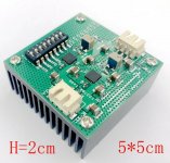
Is the pictured TPS7A4701 TPS7A3301 module a good bet? It seems to offer higher voltage ranges than the LT3045/LT3094?
Which is considered best? TPS7A4701/TPS7A3301 or LT3045/LT3094?
Attachments
Not strictly true I'm afraid. The output inductance of the LM317 reduces with increased output current. It is on one of the early LM317 data sheets and I have a graph of it somewhere. It makes a big difference to the optimum value and ESR of the load capacitor.
Maybe the exception proves the rule?
Some truth here, the LM317/337 is less sensitive to the output capacitor ESR (if too low it triggers oscillations) when the load (output current) increases. But then a regulator oscillating is a catastrophic incident, the result of serious design flaw. LM317 is not designed to use low ESR capacitors at the output, for precisely this potential stability issue. Not the case with modern regulators, most are designed to support ceramic output capacitors. Adding an output extra load to compensate for an LM317 output low ESR capacitor stability issue would be, ahem, a dumb design decision at best.
But this is not related in any way to "superior sound quality" when loading, unless comparing with the sound of a "singing" DC regulator.
Is the pictured TPS7A4701 TPS7A3301 module a good bet? It seems to offer higher voltage ranges than the LT3045/LT3094?
Which is considered best? TPS7A4701/TPS7A3301 or LT3045/LT3094?
Depends on defining "best". LT3045/LT3094 are slightly lower noise and easier to work with (due to the more DIY friendly case), TPS7A4701/TPS7A3301 do support higher voltages and output currents. I believe it is fair to say that for low voltage/low currents they are pretty much at par.
- Home
- Source & Line
- Digital Line Level
- ES9038Q2M Board