Thin aluminum is useless, it won't protect against the magnetic field (which is the evil component). Only a double steel box has any prospects to be good.
I also doubt a steel CD case would help much, any opening in the steel case, even the smallest, will allow the 60Hz and harmonics magnetic field to seep in. Make sure you electrically isolate the internal and external steel boxes and connect the ground to the external case, the internal steel box will be floating.
I also doubt a steel CD case would help much, any opening in the steel case, even the smallest, will allow the 60Hz and harmonics magnetic field to seep in. Make sure you electrically isolate the internal and external steel boxes and connect the ground to the external case, the internal steel box will be floating.
Terry,
Thanks for your kind and constructive post regarding the OPA1656: interesting as ever!
Claude
Thanks for your kind and constructive post regarding the OPA1656: interesting as ever!
Claude
Thin aluminum is useless, it won't protect against the magnetic field (which is the evil component). Only a double steel box has any prospects to be good.
I also doubt a steel CD case would help much, any opening in the steel case, even the smallest, will allow the 60Hz and harmonics magnetic field to seep in. Make sure you electrically isolate the internal and external steel boxes and connect the ground to the external case, the internal steel box will be floating.
Ok. I will forget about the aluminum. I can't use aluminum as thick as shown in the link you posted.
Since I am not familiar with double steel boxes please confirm that I have this right:
- Place the LNA in a first (internal) steel box but make no electrical connections to this first steel box.
- Place the first steel box inside a second larger box.
- Connect the larger (outside) steel box to ground.
- Connect the LNA ground to the larger (outside) steel box.
I might not have suitable boxes right now but as a first preliminary experiment would it make any sense to put the LNA inside a metal cookie tin and then place that metal cookie tin inside a heavy steel clothes dryer? I know it sounds odd but the steel chassis of the dryer is right next to my work bench and it is available for a little test... ...later I could buy a suitable all steel chassis without gaps.
Or is the metal cookie tin simply too thin and a waste of time to try?
The recycled DVD and Receiver steel chassis that I have on-hand are largely open at the front so while they are thicker they sound unsuitable for shielding.
Personally, I haven't found that I need LT3045/LT3094 to get excellent audio sound quality. The recommended circuits attached to post #3003 are pretty good as far as schematics go. Everyone I know of who tried LT3042/LT3045 for AVCC eventually found an opamp based regulator of some type sounded much better to them. Why? I don't know. Don't have time to study it.
i agree...judging by specs can sometimes be deceiving.
also, for some reason digital circuity is less harmed by noise. maybe it's due to fast rise/fall of signal.
regarding opamp buffer, i'm wondering if adding a buffer stage that is part of the loop would make it even better. After all, an opamp is not specifically made to deliver current.
...then sell those results to the gullible. A safe way to success/recognition as an audio guru, doesn't require any expenses or skills, other than putting together a nice attractive story line, that must include a set of predefined keywords.
This approach to designing audio electronics doesn't bother me at all; what bothers me is attempting to find, or invent, engineering arguments to support these uncontrolled listening impressions. When everything else fails, going as far as creating an own, private physics.
So good luck with it, no need to re-iterate the "music is more than a collection of sines" line of reasoning.
There's no need to be so aggressive. I have no intention of selling anything to anyone. I just like music and would like others to benefit from what I have found. Have you ever done double blind testing over weeks of listening? That is what it takes to really prove some of the changes we are discussing here. I started doing this five years ago as I was like you and very sceptical. I'm sure that there are simple things that you could try on your setup that could prove what I have found to be so. Are you open to trying them? Double blind if you wish. I'm happy to take this off-line with you to an email conversation so you can understand me better, rather than just being insulting. Maybe you could then offer an explanation of changes that you hear from your clearly so vastly superior knowledge and understanding.
Message me if you are interested. Otherwise please quit your trolling of me and others on this matter.
John
Terry,
To close topic on OPA1656... you are indeed right: the outputs never enter cutoff like for Class AB.
OPA1656 has a Monticelli bias whereby the outputs appear to be biased with a translinear loop, making them in fact already act like a constant current source when they are not conducting load current.
Enjoy music
Claude
Why that long?Have you ever done double blind testing over weeks of listening?
Ok. I will forget about the aluminum. I can't use aluminum as thick as shown in the link you posted.
Since I am not familiar with double steel boxes please confirm that I have this right:
Is that right?
- Place the LNA in a first (internal) steel box but make no electrical connections to this first steel box.
- Place the first steel box inside a second larger box.
- Connect the larger (outside) steel box to ground.
- Connect the LNA ground to the larger (outside) steel box.
I might not have suitable boxes right now but as a first preliminary experiment would it make any sense to put the LNA inside a metal cookie tin and then place that metal cookie tin inside a heavy steel clothes dryer? I know it sounds odd but the steel chassis of the dryer is right next to my work bench and it is available for a little test... ...later I could buy a suitable all steel chassis without gaps.
Or is the metal cookie tin simply too thin and a waste of time to try?
The recycled DVD and Receiver steel chassis that I have on-hand are largely open at the front so while they are thicker they sound unsuitable for shielding.
That is correct. It is essential to leave the inside cookie tin floating. And no worries, cookie tins are the gold standard for this type of experiment. You could of course buy a mu metal shielded box, but I somehow don’t think it will fit in a DIY budget.
Have you ever done double blind testing over weeks of listening?
Yes, but not over weeks. Anyway, I have zero interest in any private communication on this topic. If you want to be taken seriously, come up with a sharp description of your setup, and a clear description of your blind testing plan. The gold standard is to provide enough information so that anybody interested could execute the test plan and confirm (or not) your tested hypothesis.
Anything else is just anecdotical gravy.
Ritualized opinion is still just opinion. I'll stick with AP or R&S.a clear description of your blind testing plan
I see, so a week is a snapshot but weeks is the full movie? Got it.Perhaps a snapshot doesn't give much insight ?
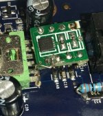
The problem with OPA1622 is that it is 10-pin device. It has a ground pin that is supposed to be connected to real ground. OPA1622 on an 8-pin DIP adapter is not good. It sorta works, but distortion is higher than it would be with the ground pin properly grounded
Very true, fortunately it's not difficult to connect the ground pin to ground.
Attachments
That is correct. It is essential to leave the inside cookie tin floating. And no worries, cookie tins are the gold standard for this type of experiment. You could of course buy a mu metal shielded box, but I somehow don’t think it will fit in a DIY budget.
Ok. I did the following:
- Placed the LNA in a first (internal) steel box but make no electrical connections to this first steel box. [Royal Dansk Cookie Tin 😀]
- Placed the first steel box inside a second larger box. [Heavy Stainless Cooking Pot]
- Connected the larger (outside) steel box to ground.
- Connected the LNA ground to the larger (outside) steel box.
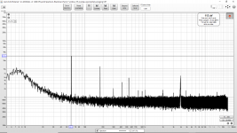
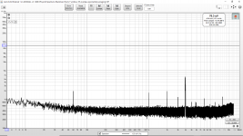
During the measurements I unplugged everything in the area including the overhead workshop light. The laptop was running on batteries.
Since it is 60 Hz (and 180 Hz) is it correct to conclude this is not from the power supply? There is no 120 Hz. (No sign of 120 Hz at all, so this is likely a clue.) I am not sure what to look for next.
The shielding experiment seemingly yielded nothing. Prior to the shielding experiment I greatly increased critical power supply caps 10x in size and ultra low ESR (should be totally unnecessary) and the 60/180 Hz did not move. (I already assumed it was not the power supply but I wanted to be 100% sure.)
Again the LNA has LM317/LM337 onboard with denoiser, plus CRC filter before those and then the rejection of the NE5534. (TL071 used as DC offset servo.) Again it is a Douglas Self MC type LNA.
Before the LNA board and external to the shielding is a second LM317/LM337 board that preregulates to +/- 20VDC. That board has nice large low ESR capacitors on input and Vadj.
Not sure what to try next. I might try swapping for high rejection ratio operational amplifiers. (I have some OPA228 and OPA277.)
Or maybe I try a different interface. Could the 60 Hz and 180 Hz possibly come from the LNA output connection to the 24 bit USB Sound Blaster Live? I would think not since the loopback is cleaner, the connection is shielded and the laptop is running on batteries.
It would be a pain but maybe I should try to run on batteries for a last test to totally rule out the input power to the LNA. Maybe I use two stacks of three 9V for a quick test.
Or perhaps I should try using a different audio interface?
Or maybe these levels are as good as it is going to get for now? The screen shots show the noise on the output of the LNA on the 60 dB gain setting. So input levels are 1000x lower.
Attachments
-
 LNA 60 dB Gain Inside Cookie Tin Inside Heavy Stainless Pot LNA Ground To Pot.png98.7 KB · Views: 252
 -
 LNA 60 dB Gain Inside Cookie Tin Inside Heavy Stainless Pot LNA Ground To Cookie Tin.png98.7 KB · Views: 242
 -
 LNA 60 dB Gain Inside Cookie Tin Inside Heavy Stainless Pot.png98.7 KB · Views: 231
 -
 LNA Off Inside Cookie Tin Inside Heavy Stainless Pot.png134.2 KB · Views: 237
Last edited:
Have you tried separating your return paths on the 0v rails? If common paths exist between +ve and -ve 0v returns between any of the 180Hz and below filtering and the transformer then lower ESR caps might even make matters worse as they can sink a higher peak current at diode switch on. Can you possibly post a sketch of everything between the transformer and regs which indicates common paths for 0v returns?
John
John
Perhaps a snapshot doesn't give much insight ?
I see, so a week is a snapshot but weeks is the full movie? Got it.
Whereas I don't know of any mastering engineers that use longer term DBT, I
believe some designers do for development their products.
Dave Hill (Cranesong) apparently uses this method. He has designed a LOT of
very respected, great sounding pro audio gear.
TCD
Rather than just dismissing out of hand what people claim to hear as being misguided, irrelevant or even deliberately misleading, wouldn't it be better to examine where and why our measurements do not explain what people claim to be hearing? For me this is just a hobby and I am tired of the aggression and arrogance of people with closed minds.
I might have particularly wonky hearing and my findings might be irrelevant to others as a result but I don't think we are in a position to prove that yet and I would like to reach that point, one way or another. Every time I hear an improvement which I can't explain I find it extremely annoying and frustrating. Some of these unexplained improvements are really quite obvious and really don't require DBT. IMHO our current crop of measurements doesn't comprehensively explain everything we hear or get the emphasis and balance right.....yet. If they did then we wouldn't be having this discussion.
John
PS If there is a DIYaudio thread already in existence where this "explaining of subjective findings" is already being discussed then perhaps some kind soul could guide me towards it. I don't want to derail this very valuable thread any longer.
Last edited:
Or maybe I try a different interface. Could the 60 Hz and 180 Hz possibly come from the LNA output connection to the 24 bit USB Sound Blaster Live? I would think not since the loopback is cleaner, the connection is shielded and the laptop is running on batteries.
It would be a pain but maybe I should try to run on batteries for a last test to totally rule out the input power to the LNA. Maybe I use two stacks of three 9V for a quick test.
For noise measurements you probably should use a sound interface that has balanced inputs/outputs. Most modern sound interfaces have them (e.g. Focusrite, Motu, Steinberg).
I would also try batteries as power source to the LNA.
Anyhow the rising noise density below 100Hz does not look good. That is probably due to the LNA design.
John Luckins,
There is not a thread were any constructive work on the problem is being done. One huge problem is the difficulty of properly testing human perception. The words of one member with professional experience in that area:
"As said before, it depends on the field; pure physical or mathematical stuff is more robust but if humans are part of the experiments, it gets way more complicated.
As cdbd mentioned the "blind tests" , these are a perfect example where experiments often look like real science but in fact are not so scientific at all."
The Black Hole......
(Blackhole Thread Post #5682)
Last edited:
- Home
- Source & Line
- Digital Line Level
- ES9038Q2M Board