. I don't doubt it at all (relative to modern parts) but I am getting nostalgic as I age and I want to build the original. I like the simplicity of the single supply architecture. Also, I have 12 2N3055s in my bin and want to use some of them. If I had MJ480s I'd be using them.perfectly happy.
If you want something close to MJ480's, consider the BD911's. Very similar in terms of power handling and fT. Critically, it has a 'low' 3Mhz fT, like the MJ480, so you won't have any issues with the sound being 'bright' or oscillations occasionally associated newer power transistors like the 2SC5200 with a 30Mhz fT.
Being newer than the MJ480, it benefits from epitaxial manufacturing process, and has better gain and most importantly, a flatter transconductance curve. This is where the MJ480/BD911's are superior to the 2N3055. Even with new 2N3055's the gain just falls of the cliff with increased current.
I recently built a 1969 amp with BD911's as a Christmas project and it sounds sweet. BD911's are cheap, so you can buy a dozen for the price of 2 pairs of 2SC5200's and pick two nicely matched pairs.
BTW, I also used the ZTX450 instead of the 2N1711. Similar gain, but slightly better current handling. Penalty of a lower Vcbo and Vceo, but that's irrelevant given the low voltages of JLH amps.
Maybe you should reserve your 2N3055's for the power supply 😀
Famous British amplifier Alto (Audio Innovations) on a modified JLH1969 circuit. It is built using discrete Darlingtons. Works in AB class.
The manufacturer's recommended quiescent current is 140mA. Output power 35w/8ohm.
The link you posted leads to a site which raised a red flag and completely blocked access.
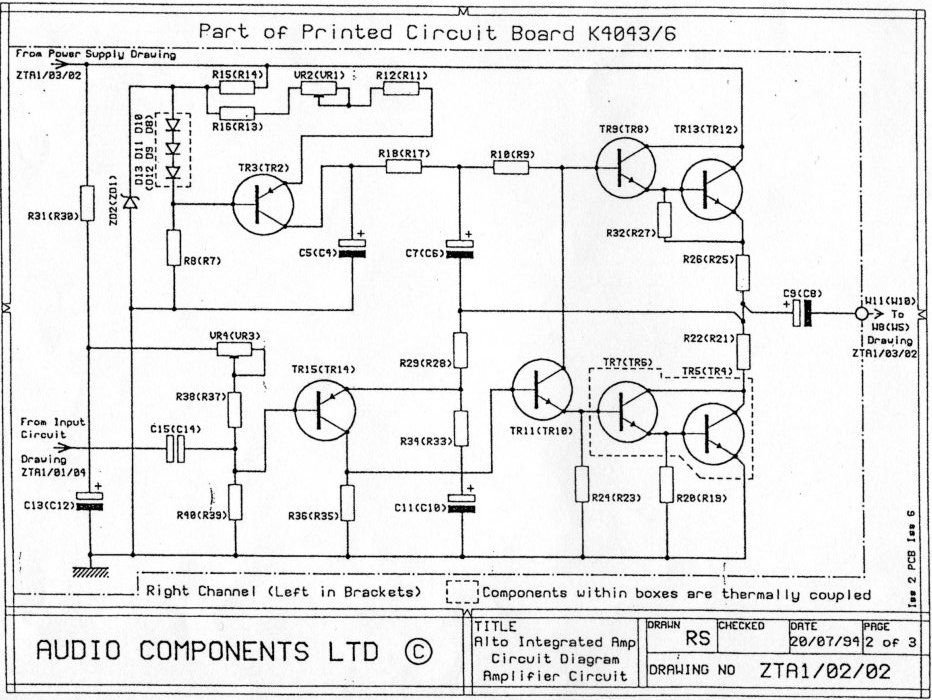
#7584 Please note the above Circuit diagram is only one channel of the main power amp section, it does not include Power supply, protection circuit, input switching or lead outs etc. Note how simple the circuit is and there are only 3 capacitors in the audio path giving very pure natural sound.
Audio Innovations Alto Myth or Truth | AVForums
Audio Innovations Alto Myth or Truth | AVForums
It looks like a bad copy of the Audio Innovations.
What is it with using the two lower half Darlingtons having emitter resistors connecting to earth. There are reasons for not using that approach with Q/C circuits and a double whammy with Darlingtons.
If you want something close to MJ480's, consider the BD911's. Very similar in terms of power handling and fT. Critically, it has a 'low' 3Mhz fT, like the MJ480, so you won't have any issues with the sound being 'bright' or oscillations occasionally associated newer power transistors like the 2SC5200 with a 30Mhz fT.
Being newer than the MJ480, it benefits from epitaxial manufacturing process, and has better gain and most importantly, a flatter transconductance curve. This is where the MJ480/BD911's are superior to the 2N3055. Even with new 2N3055's the gain just falls of the cliff with increased current.
I recently built a 1969 amp with BD911's as a Christmas project and it sounds sweet. BD911's are cheap, so you can buy a dozen for the price of 2 pairs of 2SC5200's and pick two nicely matched pairs.
BTW, I also used the ZTX450 instead of the 2N1711. Similar gain, but slightly better current handling. Penalty of a lower Vcbo and Vceo, but that's irrelevant given the low voltages of JLH amps.
Maybe you should reserve your 2N3055's for the power supply 😀
You've convinced me to go with the BD911s. This will delay the project but that's okay. I am in no rush at all.
#7588 There are several schemes on the branch. An attempt is made to develop a universal PСB. Can build 1969 Class A, Class AB with Darlingtons, Discrete Darlingtons, Triple Darlingtons and Mosfet. It is recommended to use a stabilized power supply.
There are links to the diagram of the former Millwood member 🙂
№23 JLH10W- MOSFET output
There are links to the diagram of the former Millwood member 🙂
№23 JLH10W- MOSFET output
Last edited:
You've convinced me to go with the BD911s. This will delay the project but that's okay. I am in no rush at all.
Do not forget the clamps for TO-220.
Can't I just tap holes in the heat sink for each transistor and use the existing holes in the tabs?
What is the advantage of the clamps? They would reduce the number of holes I would need to drill/tap, but is there any other advantage?
What is the advantage of the clamps? They would reduce the number of holes I would need to drill/tap, but is there any other advantage?

It has a thin plate and an offset hole.
Last edited:
Hi, Tiago! Long wires Q1\Q2 - 10-15cm. Current 1-1,2A. Power 6W/6om.
It is better to place the radiator fins vertically. Raise the radiator slightly for better cooling.
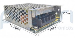
Hello OldDIY, can I connect this amplifier to a switched 24V DC (3.1A) source?
Does my amplifier support this 24V voltage?
And how do I calculate the quiescent current in the circuit?
Thanks.
Attachments


Interesting.
I found these TO-220 semiconductor package heat sink clamping bar which look like a convenient solution, and pretty affordable.
Then these, H7301 Single TO220 Transistor Clamps Pk100 - Altronics but far less convenient and $27 is a lot to pay for 100, when I only need 4.
Also, cannot find any on Mouser. I am probably using the wrong keywords to search.
Hi, Tiago! The quiescent current will remain at 1.4A. The question is that the amplifier draws both less and more current. Let's multiply by two channels - your SMPS may have protection. Choose with a current margin.
Last edited:
Interesting.
I found these TO-220 semiconductor package heat sink clamping bar which look like a convenient solution, and pretty affordable.
Then these, H7301 Single TO220 Transistor Clamps Pk100 - Altronics but far less convenient and $27 is a lot to pay for 100, when I only need 4.
Determine if you will mount the transistors on separate heat sinks without spacers, and then insulate the heat sinks. Or you will install it on a common radiator with a thermal interface. For TO-220, an additional intermediate thermal distribution plate may be required. TO-3 (2N3055) cope better with heating.
TO-220 Pras = 10W thermopath KPT-8
Temperature difference (in degrees Celsius):
- without gasket 1-2
- pink ceramics t = 1mm 5-6 (13 without paste)
- white ceramics under TO-3 t = 2mm 7
- nomacon t = 0.2mm 26 (28 without paste)
- mica t = 0.06mm 10
- oxidized aluminum plate t = 0.4mm 4-5
- AlN ceramics (thermal conductivity 180) t = 1mm 1-2
- AlN ceramics, power 20W, t = 1mm 3-4
- without gasket, power 20W 2-3
tested all gaskets and thermal compounds at 20W (24V / 0.82A)
KPT-8 paste (except for the last measurement).
Radiator area 2500cm2.
Warm-up time 5 minutes.
(T heatsink / T crystal = delta)
Direct contact without paste 47/60 = 13 degrees
direct contact + KPT-8 - 47/52 = 5 degrees
Nomakon blue (0.28mm) - 43/73 = 30 degrees - the test was forcibly stopped
Nomakon gray (0.33mm) - 45/67 = 22 degrees
Thick mica (0.08mm) - 47/66 = 19 degrees
Thin mica (0.02mm !!) - 46/58 = 12 degrees
China oxide (1mm) + KPT8- 48/60 = 12 degrees
China oxide (1mm) + MX2 - 47/55 = 8 degrees
Last edited:
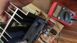
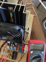
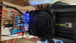
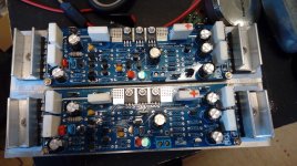
Here's the 1969 version amp I built over Christmas using BD911's, a ZTX450 and BC560. I wanted to build it fast and used whatever I had on hand, except for the audio grade output capacitors I bought earlier.
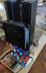
The BD911 TO220's were mounted directly onto the heatsink using old school mica and white thermal grease. There is about a 15c thermal resistance between the tab of the TO220's and the back of the heatsink.
The heatsink was largest I had at home, bought it a couple of decades ago, so can't remember its rating. Anyway, without the fan, the heatsink came up to about 75c on a 25c ambient.
The transistors were almost 90c, perfectly fine long term and sounded great (bipolar transistor gain increases quite significantly with temperature). I was more worried about the PVC insulation of the connecting wires and nylon washer I used to insulate the mounting bolt, so I put in a cooling fan pulled from an old PC. That dropped the temperatures down to a more reasonable 56c at the transistor tab and 41c on the heatsink directly at the back of the transistor.
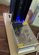
I used an 24V/3a switching power supply I had lying around, trimmed it up to 28v and biased the amp to 1.1a/channel. (The speaker I am driving is a shade over 8 ohms).
Very happy with the sound. I thought the switching PSU was going to be noisy, but heard only very faint switching noises with my ears against the speaker. The loudest is the fan, that was pulled from a retired server, so its bearings probably had a hard life. I've got a super quiet magnetic levitation vapor bearing fan on order.
The BD911 TO220's were mounted directly onto the heatsink using old school mica and white thermal grease. There is about a 15c thermal resistance between the tab of the TO220's and the back of the heatsink.
The heatsink was largest I had at home, bought it a couple of decades ago, so can't remember its rating. Anyway, without the fan, the heatsink came up to about 75c on a 25c ambient.
The transistors were almost 90c, perfectly fine long term and sounded great (bipolar transistor gain increases quite significantly with temperature). I was more worried about the PVC insulation of the connecting wires and nylon washer I used to insulate the mounting bolt, so I put in a cooling fan pulled from an old PC. That dropped the temperatures down to a more reasonable 56c at the transistor tab and 41c on the heatsink directly at the back of the transistor.
I used an 24V/3a switching power supply I had lying around, trimmed it up to 28v and biased the amp to 1.1a/channel. (The speaker I am driving is a shade over 8 ohms).
Very happy with the sound. I thought the switching PSU was going to be noisy, but heard only very faint switching noises with my ears against the speaker. The loudest is the fan, that was pulled from a retired server, so its bearings probably had a hard life. I've got a super quiet magnetic levitation vapor bearing fan on order.
Attachments

TO-220 for better heat dissipation must be additionally pressed against the radiator.
It has a thin plate and an offset hole.
You can also DIY the clamps like this 🙂
I like clamping them in pairs, because there are less screws to loosen while experimenting with the amp.
It can also be worth mentioning that the surfaces (transistor & heat sink) should be really nice and flat.
Attachments
Last edited:
- Home
- Amplifiers
- Solid State
- JLH 10 Watt class A amplifier