First thing is the Dayton RSS265 is not suitable for BP-4 alignment. One needs drivers higher Vb requirement so ports are manageable.
Sure enough, all distortion compared to sealed is lower from HP tuning down. Anywhere from 3 to 6 dB.
Sure enough, they do give the LP response further reducing mechanically produced harmonics. But, my build did to work as the drivers were not suitable.
The effect of the LP filter was lost after a couple octaves as the port is so large, the mids ( harmonics) just exit as easily as a DR. So, instead of it being what we think of as a BP, think of a ported enclosure with a notch filter on the top end.
So, slapped the pair into a sealed box. "Stuffed" away the box resonance and got the Q down. I had been advised against reversing one driver to lower even order harmonics, but it was easy to test. Sure enough, odd order went up about 1 to 1.5 dB, but even dropped by 10 dB! A worthwhile trade.
In room all eq'd up, 80 dB @ 1M above 50 Hz, THD is below 2.5 %, dropping pretty quickly below .5 From my bench testing, the BP box would have been below 1% probably to 40 Hz. Not bad as my old single sealed Titanic sub was 15% @ 40. Going to use it for further BP experiments.
Oh!!!!!?
should i be buying another 265ho4? I only have one(i see your point on why you want a bit more ‘V’ to play with, btw). It like small and thin...🙁
should i be buying another 265ho4? I only have one(i see your point on why you want a bit more ‘V’ to play with, btw). It like small and thin...🙁
I used the HF. HO is a little different
My goal was to see how far I could reduce the HD. Output was never a problem as I am not a bass freak. We already know two subs are better than one if only to smooth room nodes. This is a terrible room, small, square and can only have one sub cabinet. So sure, if you are running a single 10 inch sub, you need another. Or three. I really wish I could get it to align the way WinISD models, but not close. The Titanic seems to be an even worse driver for BP. Looks like we want a large VAS for BP-4 or our passband will be too narrow.
My goal was to see how far I could reduce the HD. Output was never a problem as I am not a bass freak. We already know two subs are better than one if only to smooth room nodes. This is a terrible room, small, square and can only have one sub cabinet. So sure, if you are running a single 10 inch sub, you need another. Or three. I really wish I could get it to align the way WinISD models, but not close. The Titanic seems to be an even worse driver for BP. Looks like we want a large VAS for BP-4 or our passband will be too narrow.
Ever use TH mode in hornresponse? its akward at first but it quickly becomes second nature as lengths are easy for the brain to decipher as ‘amounts of areas potentially active’ vs the anticipation of a helmholtz by a ‘volume developing pressure to a relief valve set point’? Sounds weird, but..?
The whole Vas thing sounds familiar, your bitten harder by a lower Fs i think too. As soon as you tune that to qw it becomes long and thin for the reasons you mentioned
The whole Vas thing sounds familiar, your bitten harder by a lower Fs i think too. As soon as you tune that to qw it becomes long and thin for the reasons you mentioned
Last edited:
Never used HS. A bit confusing at first glance. I assume the idea is you model the port as a horn? I am not a fan of horns so never learned it. Needs a couple parameters I don't usually record so will need to remeasure a driver. Help file seems to assume you know all about horns. Duh.
Went looking for drivers with higher VAS, higher Fs and still have Xmax suitable as a sub. No luck yet.
Went looking for drivers with higher VAS, higher Fs and still have Xmax suitable as a sub. No luck yet.
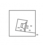
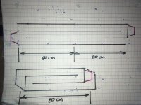
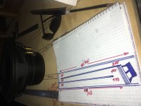
This should give you a quick start on a Hornresp sim for that driver that replaces the front chamber and vent with a reverse-taper "horn" that tunes the system correctly. The driver offset from the start of the horn is specifically set to reduce the eliminate the first (and usually most annoying) out of band resonance. The horn is folded around the center chamber holding the driver.
Attachments
What is it? Because i can blow up a bunch more pics of same basic geometry in a variety of layouts? Half of them gathering dust and half already recycled. And to suite a driver mostly (TS). But thats not whats in the details of the reality in the mystery? if i wasnt in such a rush i might have stopped to smell the roses in more detail, but its fun to build and explore... except for one thing. a solid foundation of data to compare if comparing.
They all are ‘bettter’ when ‘new’, unless a total screwup(gotta know bad before good) and if given a couple weeks in a consistent way(commuter car or office system, anything??) they all might reveal ‘transients’. Or a biased bandwidth ?
And thats why i dunno what im looking for? Because they all suck, Eventually.
But theres a mathematical solutiion in harmonics maybe? Sealed, or no back wave in a stuffed to death TL is not denied. I agree. but its kinda missing the things or energy thats usefull still?
Attachments

Last edited:
This should give you a quick start on a Hornresp sim for that driver that replaces the front chamber and vent with a reverse-taper "horn" that tunes the system correctly. The driver offset from the start of the horn is specifically set to reduce the eliminate the first (and usually most annoying) out of band resonance. The horn is folded around the center chamber holding the driver.
This will take some study. Not being a horn guy, have not even heard of a reverse taper horn, but looking at it, it might explain why my prototype was so far off the WinISD model. The port was so large in relation to the front chamber it acted like one. Much to think about.
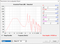
Your simulated response is much like my measured response though I had a huge 20 Hz port resonance issue.
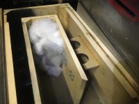
I have got a reasonable solution based on WinISD for my Titanic 10 woofer so I wil experiment with it as the example. My pair of RSS265-4's are happily installed in their cubby hole until I can learn a lot more and do better than a simple low Q cabinet. Odd driver, the RSS. Getting a Qtc of .65 was not to hard, but .5 would require an immense cabinet, virtually an IB.
Might have to pour me a nice frosty porter to study this. Cold, damp and dark but at least the snow is just north of us. Perfect for a Foothills Black Moca and a bit of Gouda cheese.
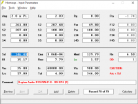
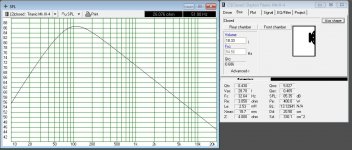
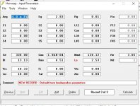
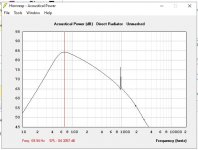
Trying to crawl before running ( why the WinISD model does not match), I loaded by Titanic 10 parameters into both HR and WinISD.
Impedance peak says they tuned to the same, but peak of the curve is way off and HR gives a peak or 42 Ohms where Win is 24. Both 52 Hz. WinISD matches the OEM plot pretty well. All values from a fresh run with my Woofer ester. ( Dats)
Can anyone see what I might have screwed up?
Impedance peak says they tuned to the same, but peak of the curve is way off and HR gives a peak or 42 Ohms where Win is 24. Both 52 Hz. WinISD matches the OEM plot pretty well. All values from a fresh run with my Woofer ester. ( Dats)
Can anyone see what I might have screwed up?
Attachments
Trying to crawl before running ( why the WinISD model does not match), I loaded by Titanic 10 parameters into both HR and WinISD.
Impedance peak says they tuned to the same, but peak of the curve is way off and HR gives a peak or 42 Ohms where Win is 24. Both 52 Hz. WinISD matches the OEM plot pretty well. All values from a fresh run with my Woofer ester. ( Dats)
Can anyone see what I might have screwed up?
Whats wrong? Youre working off the length of LRC now. winisd has nothing but a pressure and a fart to assume. i think that sealed is going to show you a peak as well as seen in the reponse at the LRC in a harmonic. but now that info is helpful. use it to troubleshoot in the future. use various as LRC to see potential issues.
Last edited:
Set Ang to be 2xPI for comparison purposes. Box modeling s/w like WinISD assumes 2PI loading.
That explains the difference in SPL, but not the difference in the center of the hump or the large difference in impedance value.
Whats wrong? Youre working off the length of LRC now. winisd has nothing but a pressure and a fart to assume. i think that sealed is going to show you a peak as well as seen in the reponse at the LRC in a harmonic. but now that info is helpful. use it to troubleshoot in the future. use various as LRC to see potential issues.
I am afraid I do not understand what you are saying. LRC to me means inductance, resistance, and capacitance. This driver is high inductance, heavy cone, stiff suspension, so very narrow passband. The question is why the two simulations have such different centers in the acoustic power.
I don't agree with having a large Vas to be a requirement for a good BP4 driver. In fact, you can have a small bandpass with a great tuning with a small-Vas driver.
Now- if you must use ports, instead of a PR, then you have to be able to fit them either interior or slot-loaded around the outside of the box. This does not mean a driver is not suitable.
Later,
Wolf
Now- if you must use ports, instead of a PR, then you have to be able to fit them either interior or slot-loaded around the outside of the box. This does not mean a driver is not suitable.
Later,
Wolf
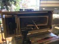
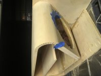
Wolf, the problem I was having with small chambers was first, vents too long, and second, my current half-baked theory, is the port was so large with respect to the chamber, exiting from the small end, it was acting more like a tapered line, not a tuned chamber. More civil box meant too narrow a passband.
By vents too long, ones you might try are in the 20 inch range so a resonance issue. Many of the nice flat wide bandpass acoustic plots come up with vents in the 100 inch range, which is flat not workable. Worst was actually 140 inches.
Put the Titanic into Bagby. Tuning came out the same. Magnitude of impedance spike about half way between HR and WinISD. Bagby does have entry for box leakage and stuffing, the others do not. HR has parameters for lining, but I left that out as the others do not. I remember some value from Small related to box size loss factor that none of them seem to have unless they are guessing behind the scenes. Need to go re-read Smalls AES paper. It gave us which column in the Bullock charts to use. Darn, that was 40 years ago! Bagby does not show the HF roll-off I know is real, so that is an error. Estimate of the hump, if it had the rolloff, woudl be about half way between as well.
So three tools, same data, three results. I guess I need to go fishing as I got me a can of worms.
That explains the difference in SPL, but not the difference in the center of the hump or the large difference in impedance value.
I was about to say Hornresp does not include the impact of box losses in its sims, but I think a recent update did include it for vented alignments. I don't know how to check to see if it's on or off though.
I am afraid I do not understand what you are saying. LRC to me means inductance, resistance, and capacitance. This driver is high inductance, heavy cone, stiff suspension, so very narrow passband. The question is why the two simulations have such different centers in the acoustic power.
LRC , in horn response is length of rear chamber. Its also the spike shown in the responce if you math it out into the harmonic or equivalent fractions in length. increasing unwrapped shown if looking for clues in other ways like 8tth order qw pipe or a sealed box or a TL, etc as folded segments
Look at red LE, use black LE, manually enter the BL of red LE however...
Check Qes in both. Look at the re/le ratio and shuffle them
To see the variety of results. Theres impedance. Its not unlike a dvc vs single if you accidentally use the wrong entry. might look vaguely similar.
Last edited:
I intend to over ride the issue of the band width issue. Two folds eat it as 3 segments aimed at it. Or away from it depending on how wrong i decide to try and compare to an experimental baseline reference. The sim can be very nasty so theres no questions asked here. No ‘path’ almost all exact folds, only offset or turning centerlines to skew the resulting impedances or the simmed results. this was suppose to be exactly twice this as a halfwave form split into a full
and quarters, but if we cut it into this its a well known offset driver TL with no distractions like ‘path’ or questions in folding.
and quarters, but if we cut it into this its a well known offset driver TL with no distractions like ‘path’ or questions in folding.
Attachments
Last edited:
- Home
- Loudspeakers
- Subwoofers
- Lessons learned from my sub build