during playing card and other games to wait for the count down.😀..i am thinking about the "floating" SMPS:
my LRS150-24V is earth GND at the housing, but the output terminals not...for sure. connection is: with the cable i go to the amp and there is the GND at the +output terminal by the amp housing. but the real earth GND comes by my DAC with earth at the RCA connectors.
is that the loop?
but why at the Rchannel and not at the L channel
It is so difficult to say for sure without actually seeing it all, and this is why you need to run this suspect channel in complete isolation as a test.
That means having just the24 volt power supply connected, a signal source and a load, all wired as they should be to the board terminals.
This ensures it is run as an individual unit without any effects of loops. Grounding a stereo circuit at multiple points to a chassis can all be the cause of problems as well.
If it still distorts then you have a weird issue with the actual build of that channel, if it doesn't then it looks like the wiring is suspect.
Hi Mooly
i follow your instruction:
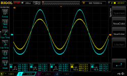
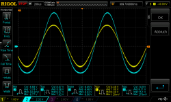
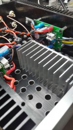
here are some pics/measurements about my R channel with 24V supply and just this channel was connected, means RCA just at R ch, load 4R at R channel, L channel completely disconnected.
finally i got after my 4A fuse at the amp and connections 23,82V at the amp board.
bias is 1,57A and AP is 11,20V
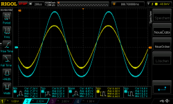
pic 1 Rchannel Supply 23,82_1500mvrms
pic 2 Rchannel Supply at _23,82_1540mvrms
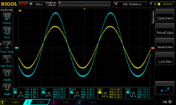
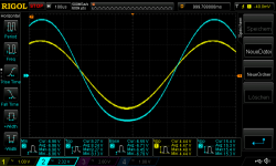
compared to the L channel
pic 3 +4
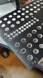
i am thinking that at this clone pcb this strange diode is doing something strange...
pic 5 left buttom corner FR207 no idea what this diode is doing...😕
i follow your instruction:
here are some pics/measurements about my R channel with 24V supply and just this channel was connected, means RCA just at R ch, load 4R at R channel, L channel completely disconnected.
finally i got after my 4A fuse at the amp and connections 23,82V at the amp board.
bias is 1,57A and AP is 11,20V
pic 1 Rchannel Supply 23,82_1500mvrms
pic 2 Rchannel Supply at _23,82_1540mvrms
compared to the L channel
pic 3 +4
i am thinking that at this clone pcb this strange diode is doing something strange...
pic 5 left buttom corner FR207 no idea what this diode is doing...😕
Attachments
-
 Rchannel Supply 23,82_1500mvrms.png49.5 KB · Views: 374
 -
 Rchannel Supply at _23,82_1540mvrms.png47.9 KB · Views: 360
 -
 L channel Supply at _23,82_1540mvrms.png49.7 KB · Views: 357
 -
 L channel Supply at _23,82_1540mvrms_detailed.png45.6 KB · Views: 319
 -
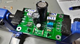 zerozone_mod1_1_ukz10uFinput_diode marked.jpg111.2 KB · Views: 306
Where is that diode on the circuit because that means the design is different to the ACA.
What parts does it connect to or connect between ?
What parts does it connect to or connect between ?
hi mooly
no idea. maybe allan knows it....but..
i just have these 2 pcb mounted in the amp and i have to reverse engineer from photos in the internet
2 PCS PASS ACA Stereo 5W Single Ended Class A FET+MOS power amplifier PCB/DIY kit/Finished board|Amplifier| - AliExpress
no idea. maybe allan knows it....but..
i just have these 2 pcb mounted in the amp and i have to reverse engineer from photos in the internet
2 PCS PASS ACA Stereo 5W Single Ended Class A FET+MOS power amplifier PCB/DIY kit/Finished board|Amplifier| - AliExpress
OK, just clarify this then.
Your boards were obtained already built up with parts fitted or at least with the parts supplied with them?
So we do have the possibility of parts on unknown provenance in that case.
Is the diode across the power supply or in series with the power supply as some form of reverse polarity protection?
Your boards were obtained already built up with parts fitted or at least with the parts supplied with them?
So we do have the possibility of parts on unknown provenance in that case.
Is the diode across the power supply or in series with the power supply as some form of reverse polarity protection?
Where is that diode on the circuit because that means the design is different to the ACA.
What parts does it connect to or connect between ?
It feeds the Drain of Q4 off the +19/24 volt line. There is no C4 (10uF) cap.
It feeds the Drain of Q4 off the +19/24 volt line. There is no C4 (10uF) cap.
Thanks Alan. I wouldn't have thought such a diode would cause distortion but its inclusion is a mystery.
I think the whole board and the component types probably need to be gone over very carefully. We know the basic design itself is tried and tested and works well.
It feeds the Drain of Q4 off the +19/24 volt line. There is no C4 (10uF) cap.
thank you to all for your help
ok. thx. so why is that diode insde??. i will short this diode...
components:
i measured all components and they are ok. caps are all from my boxes. what i checked looks the same as the schematic....instead of the diode and C4(power supply).
yes this is a clone and this board i shrink-ed to a very small size with the disadvantage that its not easy to measure the voltage at Q3 and Q4.
chris
Last edited:
...without diode(shorted) + heat update 2
Hi
i put out the diode at this clone pcb and short this area..the amp is working well
measurements looks bit better...
4R max input 1540mVrms input..before clipping
pic 1 L channel Supply at _23,82_1540mvrms_without diode
pic 2 R channel Supply at _23,82_1540mvrms_without diode
thanks to MJF for that idea..
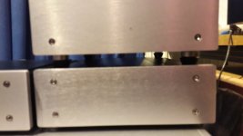
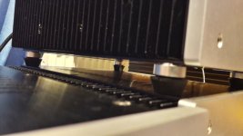
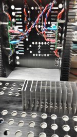
pic 3,4,5,6 are heat update with a small 50mm high heat sink what i have at home😀
chris
lets have a listening session...🙂
Hi
i put out the diode at this clone pcb and short this area..the amp is working well
measurements looks bit better...
4R max input 1540mVrms input..before clipping
pic 1 L channel Supply at _23,82_1540mvrms_without diode
pic 2 R channel Supply at _23,82_1540mvrms_without diode
thanks to MJF for that idea..
pic 3,4,5,6 are heat update with a small 50mm high heat sink what i have at home😀
chris
lets have a listening session...🙂
Attachments
-
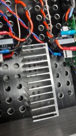 24V heat update_6.jpg238.2 KB · Views: 129
 -
 24V heat update_5.jpg228.2 KB · Views: 277
 -
 24V heat update_4.jpg250 KB · Views: 273
 -
 24V heat update_3.jpg193.9 KB · Views: 279
 -
 R channel Supply at _23,82_1540mvrms_without diode.png49.9 KB · Views: 274
 -
 L channel Supply at _23,82_1540mvrms_without diode.png49.9 KB · Views: 275
What is puzzling though is if one board has this obviously visible 2nd harmonic distortion and the other does not.
The only other realistic test now is to test both boards separately in the same test setup, in other words swap the boards over.
The only other realistic test now is to test both boards separately in the same test setup, in other words swap the boards over.
Good Evening Mooly
hmm... yes you are right. strange..
because of this diode in the first transistor Q4.
i think that this K30A FET what was at this kit is maybe the reason. i found just this datasheet...i am not sure if i have the GR version, means with 2,6...6,5mA.
chris
hmm... yes you are right. strange..
because of this diode in the first transistor Q4.
i think that this K30A FET what was at this kit is maybe the reason. i found just this datasheet...i am not sure if i have the GR version, means with 2,6...6,5mA.
chris
Attachments
i suspect that the diode is used as a safeguard against inadvertent reversing of psu leads, the amp will not work when that diode is put in reverse of the psu leads are reversed..
the smps will simple fold back and stop...
the smps will simple fold back and stop...
Last edited:
XLR Jack Pins
I built two ACAs version 1.8 because I want to use each as a bridged monoblock in a stereo setup, one per speaker. I would like to connect them to my preamp via the XLR connectors. My preamp is a Bryston BP26 that is wired with pin 1 as ground, pin 2 as positive, and pin 3 as negative.
Is the Bryston's XLR pin assignment compatible with the ACAs'? I am totally ignorant about this so I am relying on the knowledge (and kindness) of strangers.
TIA,
Jim
i suspect that the diode is used as a safeguard against inadvertent reversing of psu leads, the amp will not work when that diode is put in reverse of the psu leads are reversed..
the smps will simple fold back and stop...
good morning
good idea...a kind of protection..
after compare sound session yesterday i am now more satisfied with the sound of ACA. its more clearer in the middle and i got now more "detailed" sound, i mean more micro details at high hats and so. also the arrangement of the sound stage is yet better.
before it was a strange..sometime i got the feeling that the singer moves during singing and i miss some "upper" information.
chris
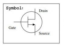
The 2SK30 FET dates back to the 1970's and was common in tuners and so on of that era.
That data sheet is just bizarre tbh, even the symbol is wrong 😀 You just don't know what these parts are and how they behave. I'm going to say the same applies to the power FET's as well.
There are to many unknowns with this.
That data sheet is just bizarre tbh, even the symbol is wrong 😀 You just don't know what these parts are and how they behave. I'm going to say the same applies to the power FET's as well.
There are to many unknowns with this.
Attachments
i still have the original 2sk30's in my parts bin.....will get the modern versions and try to compare
Last edited:
- Home
- Amplifiers
- Pass Labs
- Amp Camp Amp - ACA