Does this solve the TRIAC holding issue?
Is this done from the software only or is there a schematic used?
If I gave you a pic source code file, could you simulate that by itself without a schematic?
I just finished some coding and it assembles fine, but haven't done any actual testing yet. Maybe you could give it a first whirl to see if I screwed anything up.
Just a safety comment. The data sheet says that a MOV is recommended.
Hey P-A, what datasheet was that from?
I suppose in case something ugly comes in from the mains, the mov would just cause the fuse to blow.
Here is my latest (untested) zipped asm file, in case it can be simulated as is.
This one should do a pulse train of 250/250us duty cycle for the whole duration the triac is to be turned on. But stop short of the end of the half waves, a little before the next crossing.
The only difference compared to my working previous version is that it now gives the triac a train of pulses instead of a single fixed width of 250us pulse.
I have pcbs coming soon, as I posted at the top of the thread, so eventually I will try this out for real.
Too bad I don't have a big enough toroid to test this on for now though.. It's only a 200VA. But that was working just fine with it.
Attachments
Is this done from the software only or is there a schematic used?
No, just the software, instead of doing pulses, I could do a longer pulse while progressing the phase sweep, still turning the TRIAC off 1ms before the next ZC trigger occurs. As long as it is possible to do a longer pulse, why would I do the pulses, I can do them, of course, I will decide once I am testing the real HW.
If I gave you a pic source code file, could you simulate that by itself without a schematic?
There is sth wrong with your code, you are doing the opposite thing here and there. Your very first pulse starts immediately after the ZC. You are also missing ZC triggers. It sounds like you are not synchronized to the ZC pulses, somehow, your pulses are overlapping with moment the ZC trigger and continue to the next half-wave.
Here is your simulation:

Here is mine:

Neat idea. One thing, though: It seems you're running a lot of gate current in your TRIAC. With a 22 Ω gate resistor, you get over 10 A of gate current. Isn't that a tad much? (Sorry if that's been addressed already).
With an inductive load, you should in theory get zero inrush current if you turn on the voltage at the peak of the sine wave. I wonder if you can find an optimum turn-on point.
You may find this handy for your debugging and characterization:
The $10 Current Probe - How to Measure Current with an Oscilloscope – Neurochrome
This could be handy as well:
HP (1982b) An Inproved ac Power Switch. HP Journal 12/1982, 34-40. Downloaded from: http://hparchive.com/Journals/HPJ-1982-12.pdf
Specifically, note that HP used a pulse transformer for tighter control of the TRIAC. That'll come in handy near the zero crossing on the mains voltage.
Not to rock your boat completely, but the simple RC reset circuit is not that reliable. I recommend using an actual power-on reset circuit for this. TI TLV803E would be an example. The RC won't reset your uC on a brown-out, for example, which could lead to some unpredictable behaviour. If the PIC doesn't have a built-in POR circuit, I'd use an IC for that. They're pretty inexpensive.
Tom
Last edited:
There is sth wrong with your code, you are doing the opposite thing here and there. Your very first pulse starts immediately after the ZC. You are also missing ZC triggers. It sounds like you are not synchronized to the ZC pulses, somehow, your pulses are overlapping with moment the ZC trigger and continue to the next half-wave.
Something looks odd, but it's not what you think.
Actually the software is very much like earlier and nothing much has changed except for the extra pulses sent to trigger instead of a single short one.
So if something really is wrong, it's more likely to be timing from the delays that may be adding a small error that adds up and overflows somehow.
But I will test this without a triac first, just to look at the trigger signal.
Neat idea. One thing, though: It seems you're running a lot of gate current in your TRIAC. With a 22 Ω gate resistor, you get over 10 A of gate current. Isn't that a tad much? (Sorry if that's been addressed already).
In fact, bryston use the same value in their amps. So if that was wrong, we'd know it.
With an inductive load, you should in theory get zero inrush current if you turn on the voltage at the peak of the sine wave. I wonder if you can find an optimum turn-on point.
You are forgetting one small detail though: the toroid isn't alone all by itself to power up. It has a load, and that changes everything.
With an inductive load, you should in theory get zero inrush current if you turn on the voltage at the peak of the sine wave. I wonder if you can find an optimum turn-on point.
As you have already mentioned, this is in theory, but in real-world applications this will be different depending on the transformer power and load on it, which will need a peak current meter to read the actual peak current where the inrush limiter has a potentiometer to change the delay to meet the exact right settings for this specific transformer, which renders this method tedious to calibrate correctly.
Something looks odd, but it's not what you think.
Actually the software is very much like earlier and nothing much has changed except for the extra pulses sent to trigger instead of a single short one.
Frankly I have not looked at your code, but it is recommended to use a timer interrupt in case you need signals to be truly aligned, and periods to be accurate. Hence, start a timer, PWM ON, when timer overflows, PWM OFF.
In fact, bryston use the same value in their amps. So if that was wrong, we'd know it.
Do you know what Bryston did in their code to be so sure that this resistor value is Ok? I looked at the datasheets of these optocouplers, seems Bryston uses very small pulses to avoid a long period of high current in the opto-Triac part of the optocoupler, look at the time for which a high current is allowed in the datasheet, peak repetitve current is 1A for 100us, not 250us.
In earlier models of Bryston power amps, before they drove the triac gate from a PIC microcontroller, Bryston used an off-the-shelf TDA1085C motor controller to implement soft start. They figured: soft start for big AC motors, ought to be good enough for big toroidal transformers too.
You could buy one of these chips (B+D has them in stock) and observe its operation on a scope. Then program your PIC to do the same thing.
_
You could buy one of these chips (B+D has them in stock) and observe its operation on a scope. Then program your PIC to do the same thing.
_
Attachments
In fact, bryston use the same value in their amps. So if that was wrong, we'd know it.
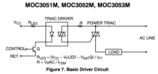
Maybe. Maybe not... I've attached the "typical application" schematic from ON Semiconductor's MOC3052 data sheet. Note the equation: R = VPAC/ITSM.
For 240 V ±10 % operation, you're looking at VPAC = 374 V worst case. ITSM = 1 A according to the MOC3052 data sheet. --> R ≥ 374 Ω. I'd use 390 Ω as that's a standard value.
Maybe I'm missing something. We all make mistakes at times. But I suggest measuring the voltage across that gate resistor to ensure that you don't overstress the TRIAC or the optocoupler.
You are forgetting one small detail though: the toroid isn't alone all by itself to power up. It has a load, and that changes everything.
I wholeheartedly agree. I didn't forget, actually. All I suggested was that you might be able to find a good spot to turn on the soft start if you experiment with the turn-on timing and monitor the current into the transformer with a current probe.
Should you end up needing tighter control of the TRIAC, in particular near the zero crossing, you may find the HP article I linked to earlier helpful.
Another possibility is to use MOSFET switches instead of a TRIAC. It's more expensive, but allows you to turn on/off the current at arbitrary points on the mains cycle. Cost shouldn't always be the driver of circuit design. I'm 100 % in favour of having a bit of fun with this. 🙂
I apologize if my post last night wasn't as helpful as it could have been. I've actually spent quite a bit of time and effort in the realm of soft starts. You may find my Guide to Soft Start Design useful. Whether you choose to follow any of my suggestions is entirely up to you. It's your circuit after all. 🙂
Peace. Happy new year.
Tom
Attachments
Last edited:
With the added complexity of triac based "soft start" solutions, what are the advantages of that approach over circuits that use time delays and relays to bypass power resistors and/or thermistors?
Many soft starts use an NTC to limit the inrush current. The main issue there is that the NTC needs to run pretty hot (~100 ºC) for it to get low enough resistance to "be out of the circuit" when it's done serving inrush duty.
The NTC also needs to cool off before it's ready for inrush duty again. This means you don't get any inrush limiting on a short power glitch, so a power glitch will blow the fuse in your equipment. Not cool!
So what to do? Many use two relays: One that turns on the NTC inrush limiting path and another that bypasses that path. Great, except relays arc. This arcing will reduce the relay life. A TRIAC provides a solution to this as it doesn't arc. Also, if you control the timing of the TRIAC and bypass relay appropriately, you can completely eliminate the relay arcing both on power-up and on power-down.
You can control the timing with some glue logic and some RCs, but micro controllers will cost less than the glue logic and allow for the implementation of more functionality and features. So using a micro controller to control the TRIAC/relay timing actually does make sense.
Many, myself included, stop here. Some draw the logical conclusion that if you already have the TRIAC and micro controller, you might as well make a dimmer of sorts that turns the load on gradually. That would save the NTC (which even at decent quantities is pretty expensive) and potentially also the relay.
My goal was to design a soft start that would work well both with a transformer-based supply (some combination of inductive/capacitive load) and with an SMPS (capacitive load).
As I touched upon earlier, an inductive load should see the lowest inrush current if you turn it on when the mains voltage is at its peak. A capacitor input supply, on the other hand, would need the voltage to be turned on at the zero crossing. And as 'spookydd' points out, a transformer-based supply probably falls between the two.
I through through quite a few scenarios before concluding that all of them would be more expensive than the NTC+TRIAC+relay solution, so I went back to that.
I was looking to make a circuit that I could sell, so cost was a factor. Cost does not always have to be a factor. An important factor in DIY is fun. If it isn't fun, it's often not worth doing. Over-engineering something can be fun. So what if it throws 10 lb of dung into a 5-lb bag? 🙂
As for using power resistors in soft starts: That's not such a hot idea. The instantaneous power dissipated in those resistors is substantial. You really need to choose the resistors carefully to avoid over-stressing them. An inrush limiter NTC is a better choice as it's made for the purpose and allows for faster charging of the power supply. This allows the NTC to be bypassed long before a resistor-based inrush limiter would be.
Tom
Last edited:
In theory, for a 230V system it should be something like 330ohm (V^/Itsm or V^/Igm), but IIRC, early versions of the (then) Motorola applications of the MOC30xx often showed lower values (100ohm, or maybe 47ohm).Neat idea. One thing, though: It seems you're running a lot of gate current in your TRIAC. With a 22 Ω gate resistor, you get over 10 A of gate current. Isn't that a tad much? (Sorry if that's been addressed already).
The reasoning is probably that in the darlington-like configuration, the main triac conducts quickly enough to remove the current from the opto and the gate.
330ohm is probably safer, but with low sensitivity triacs, it will require a relatively high A1-A2 voltage before the triac is able to conduct, meaning the soft-start won't be able to start from exactly zero; probably of no practical importance.
Page 2 of this application note shows interesting information about snubbers for inductive loads:
https://www.onsemi.jp/pub/Collateral/AN-3003.pdfJP.pdf
Another advantage of using a microcontroller is: you can implement any child-proofing flowchart that you want. Post #8 of this thread (link) describes one simple idea, but that's just one idea. Remember, you can do anything in software. Be creative, be idiosyncratic, be obscure. The point is to make it possible for Daddy to turn on the music box but impossible for InquisitiveToddler to do the same. Thwarting a simple "monkey see, monkey do" action memory would be a good first step. You can use a pin-jumper or a DIP switch to enable/disable these sorts of things, just in case Toddler some day grows up to be trustworthy and no longer a danger to audio gear.
_
_
Last edited:
In theory, for a 230V system it should be something like 330ohm (V^/Itsm or V^/Igm), but IIRC, early versions of the (then) Motorola applications of the MOC30xx often showed lower values (100ohm, or maybe 47ohm).
If you allow for ±10 % mains variation, you end up at 360 Ω for 230 V operation. Just saying... 🙂
It could be that 1 A is the max continuous current. It probably says in the data sheet, but I'm too lazy to go look right now. 🙂 With mains voltage, the optocoupler will see a sine shaped current. But still that only buys you ~30% margin.
Elvee, how can I differentiate low/high sensitivity triacs during parts selection?
There's a minimum gate current spec in the data sheet for the TRIAC. Lower current -> more sensitive, but also more sensitive to noise. Noise can cause false triggering of the TRIAC. That's probably not a huge concern in audio applications, but that's the trade-off.
Another advantage of using a microcontroller is: you can implement any child-proofing flowchart that you want. Post #8 of this thread (link) describes one simple idea, but that's just one idea. Remember, you can do anything in software.
Yep. That post was part of the inspiration for the child lock feature in my Intelligent Soft Start. I added LED dimmers, support for various types of power switches, and other features as well. As you said, once you get the micro controller going, let the creative juices flow.
Speaking of micro controllers... One interesting idea would be to monitor the inrush current with a current sensor IC and control the TRIAC according to how much current is flowing. The sensor ICs are not overly expensive. It would allow you to make a self-calibrating optimal inrush current limiter.
Tom
It is the peak current rating, but the opto will never a sine current: just short pulses, the time for the main triac to enter full conduction.It could be that 1 A is the max continuous current. It probably says in the data sheet, but I'm too lazy to go look right now. 🙂 With mains voltage, the optocoupler will see a sine shaped current. But still that only buys you ~30% margin.
Depending on the application (the load of the main triac for example), the opto might never see a high peak current, even with a low value limiting resistor, but that has to be ascertained in a robust way because getting it wrong would result in early failure (not immediate though)
I haven't encountered any issues in the tests I've done, although those have not been done with a fully loaded psu on the toroid's secondary side.
I looked again at most of bryston's amps and they use 22ohms in almost all of their amps for the triac's gate, except for that 2b5 where it's more funky, with a 3ohms res activated by a relay, which I assume might be turned on when the triac is to be permanently turned on. And they even have one other relay that takes out the snubber, which I don't see the reason for. Weird.
I was doing some testing with a pic on a breadboard to tweak the delay routines to be more accurate and I ran into some issues with bad contacts, which caused some glitches during pic programming, and now I can no longer program that pic, because it has a bad id and calibration. Drats!
I'll have to wait for my pcbs to come in so I can do the testing with a more reliable circuit.
Is there a way to perform a bulk erase on the PIC. I.e. an erase function that wipes everything, including oscillator settings and such. A bulk erase could possibly bring it back to life.
Tom
Tom
- Home
- Amplifiers
- Power Supplies
- PIC based stand alone soft start