indianajo, thanks.
I've had the manual, The SDS board, renders it almost useless, for lead dress
with the SDS Cap board.
To change lead dress, I'd have to rotate the board 360* so all the wire connections
would come up from the bottom of board.
Leads are twisted where possible, that's supposed to cancel out noise, hum, etc, yes?
I put .1uf 630 V panasonic film cap for supression across the bias diode, then removed one leg as a check, it didn't make a difference.
Still has 7199s.
Yes, Dynaco put inputs on opposite side of amp.
I can't recall which diode I used for bias, UF glass passivated, or soft recovery I think.
It was one of the best on the list that Mark Johnson published in Linear Audio, etc.
I would assume if it was the source when I removed the Cap Board,
something would have changed it didn't.
It's 60Hz hum in the amp, no 120 Hz.
I'll have to look around for a standard 1n4007 diode.
So I guess I want a low, slow, diode for bias.
Hmmm, I have some NOS ITT geranium diodes,
(I think similar to 1N14) or some old RCA Si plug
diodes from old Fender amps of early 70s. Those are
metal cased.
Even chop sticking the various leads in the amp when it's running,
didn't change hum, quality except putting that little bamboo piece
on those nice German RAC inputs.
I don't know if I have any 33 to 68 pf ceramics at hand, and putting
them across signal to ground, like the 470K resistors, you say won't
hurt. It's worth a try, I think I only have some 50pf Mica's.
And I do have some RF Mica's in that value, the flat ones.
Tony, I know 60 Hz, with only the Si bias diode with cap across it at that.
The cap didn't make a difference.
So if those wires are the cause, can't I just wrap a loose wire coil
around them and only ground one end of the coil? Do I wrap
ClockWise or CounterClockWise?
Cheers,
if you can use a pair of wire for b+ and ground return emanating from the cap board and twist them, that might help, i use this tactic when wiring my tube amps if it is practical to do...otherwise i use a central grounding from #12 copper ground buss, insulated from chassis and connect all ground return wires to that buss...
No. Twisted pair is nice but your lead dress probably not working. Lengthen the leads as necessary to get them further away from the left 7199 input stage. Use 600 v rated wire for the high voltage wires, anything for the heater wires. this may not work, but it is inexpensive.To change lead dress, I'd have to rotate the board 360* so all the wire connections
would come up from the bottom of board.
Leads are twisted where possible, that's supposed to cancel out noise, hum, etc, yes?
I put .1uf 630 V panasonic film cap for supression across the bias diode, then removed one leg as a check, it didn't make a difference.
I can't recall which diode I used for bias, UF glass passivated, or soft recovery I think.
I'll have to look around for a standard 1n4007 diode.
So I guess I want a low, slow, diode for bias.
Hmmm, I have some NOS ITT geranium diodes,
(I think similar to 1N14) or some old RCA Si plug
diodes from old Fender amps of early 70s. Those are
metal cased.
,
Germanium diodes are seriously not for rectifying 450 vdc. - 50v bias can be a 1n4001. I used a 1n4003 to replace the selenium rectifier, no problem.
You want a high voltage standard recovery diode for 5AR4 backup, salvage one out of a computer CRT terminal or an old glass tube TV. Nobody stocks the high voltage ones with the 1" long case. 1n4007 has the right specs but will short across in coastal environments after dust gets on the short case.
.1 uf film caps do not have the radio frequency supression of ceramic capacitors. Wound ones have too much self inductance. Stacked film might be better. I haven't seen the specs.
Per Mr Tecson's post, I think that red wire over to the choke is the B+. I can't read the label on the SDS board. It is naked, unpaired. Do what Mr Tecson said, also do something about the B+ back from the choke. The wire run from filter cap to choke is about 3" in the original. The wire run from SDS board filter caps to choke is about 12". That is a big difference.
Frankly I'm not convinced massive filter caps help a ST-70 that much anyway. The peak power requirement in classical music is milliseconds for a piano hammer strike or a drum hit. The OEM filter cap can handle that. the ST-70 won't put out 35 watts for seconds at a time on techno or house "music", but if you want to play that, buy a class D amp. The main limitation of the ST-70 is the 7199 board which causes 1% HD. A different driver board that uses 3 dual triodes in a "marantz" configuration is alleged to get HD down to .x% or so. The ST-70 transformer has the capacity to drive the extra tube, if it is not driving two PAS1 preamps through the front sockets. I bought such a board from classicvalve.ca and the 6SN7 tubes sockets & parts, but the burglar carried them off to the copper scrapper 9/14. He left the ST70, which is worth $800 in burnt condition on ebay. ????
Last edited:
Thinking here, so bear with me please.
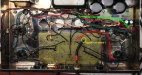
In Post 17 pic, I made a shorter B+ wire from
pin7 to the SDS board right where you see
two red wires form an x, almost out of pic.
Red-wht it is. You can just read RCa and Ind1 is partially covered up.There is only one ground on the
board, that is where the 47K ohm resistor and
you can just see a solid gray wire, goes to the
ground buss. I'm not sure I could twist them.
I'm not interested in replaced the 5AR4. Only the
bias diode. I think I have a 50pf silver mica or
some ceramics. I've got some small little yellow
fellows who's price has gone up, but they are only
.1 50V, I think possibly .1 100V for chip amp
and opamp board stuff.
The two longest runs in the amp are the choke to SDS board
(Gry, Gry-blk) and the pink(org)-wht and wht to eyelet 20, eyelet19.
Board is post #16 graphic. It takes a bit to figure it out.
No, red wire by the choke is the positive feed for the Transformer.
one on the right channel by the choke, and the left channel goes
under the board.
Now if your talking about the two wires going to the board, pink and
white, yes I have mil spec teflon silver wire...I can make a run that would go
under the mess of wires and run it under those by the power transformer,
pass the far bias pot and run them down the eyelets 19, & 20.
I figured I'd wait to replace the 15.6Ohm resistors
with 10 Ohm resistors, for simpler bias measurements.
I don't want to make unecessary changes until it works.
Question then what about CT wires, keep panasonics there?
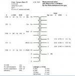
I did find this seeking out solutions, it's a good measurement
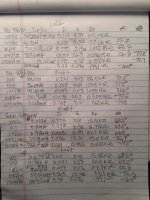
of the output Xfrmr. Then I'll post a pic of my own measurements
taken with the DER5000 LCR Meter. Not quite in the same league
as the Wayne Kerr LCR. I think the bottom two sections were the
most consistent. I didn't short the outputs. Measurements were on
the empty tube sockets.
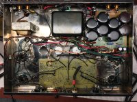
Here, we don't need to scroll around, I think I got all the relavant
pics attached.
Cheers,
In Post 17 pic, I made a shorter B+ wire from
pin7 to the SDS board right where you see
two red wires form an x, almost out of pic.
Red-wht it is. You can just read RCa and Ind1 is partially covered up.There is only one ground on the
board, that is where the 47K ohm resistor and
you can just see a solid gray wire, goes to the
ground buss. I'm not sure I could twist them.
I'm not interested in replaced the 5AR4. Only the
bias diode. I think I have a 50pf silver mica or
some ceramics. I've got some small little yellow
fellows who's price has gone up, but they are only
.1 50V, I think possibly .1 100V for chip amp
and opamp board stuff.
The two longest runs in the amp are the choke to SDS board
(Gry, Gry-blk) and the pink(org)-wht and wht to eyelet 20, eyelet19.
Board is post #16 graphic. It takes a bit to figure it out.
No, red wire by the choke is the positive feed for the Transformer.
one on the right channel by the choke, and the left channel goes
under the board.
Now if your talking about the two wires going to the board, pink and
white, yes I have mil spec teflon silver wire...I can make a run that would go
under the mess of wires and run it under those by the power transformer,
pass the far bias pot and run them down the eyelets 19, & 20.
I figured I'd wait to replace the 15.6Ohm resistors
with 10 Ohm resistors, for simpler bias measurements.
I don't want to make unecessary changes until it works.
Question then what about CT wires, keep panasonics there?
I did find this seeking out solutions, it's a good measurement
of the output Xfrmr. Then I'll post a pic of my own measurements
taken with the DER5000 LCR Meter. Not quite in the same league
as the Wayne Kerr LCR. I think the bottom two sections were the
most consistent. I didn't short the outputs. Measurements were on
the empty tube sockets.
Here, we don't need to scroll around, I think I got all the relavant
pics attached.
Cheers,
Attachments

Last edited:
Hum that is 60Hz . . .
If you double the first filter capacitor in g1's negative grid bias circuit, and then the hum goes UP, instead of going down . . .
that means the hum is from the ground loop of the bias circuit.
Return the first bias filter capacitor's positive lead Directly to the Center Tap of the Power transformer's B+ secondary.
I hope that makes sense.
480 uf load on a 5AR4 seriously exceeds the maximum capacitance rating. Eventually it will arc across & burn. 5AR4 are $18 plus $12 freight last time I bought one. People that keep the 5AR4 but want 480 uf capacitance back up the diode action of the 5AR4 with silicon diodes. Thus the 5AR4 provides slow turn on to not hammer the signal tubes with B+ when cold. The silicon diodes do the rectification..
I'm not interested in replaced the 5AR4. Only the
bias diode.
Silver wire versus copper wire doesn't matter at audio frequencies. What matters to 450 v currents is that the label on the wire reel says it is rated for 600 v.
What I did to replace the can cap B+ was screw a cinch solder terminal strip under the can hole. Same device as you used for the negative bias diode. Then I put one 33 uf and three 22 uf 450 v electrolytic axial lead capacitors above the deck. Negative leads were out, plus leads were in center away from the steel deck. Dropping resistors were on the terminal strip under the deck. If you did this you could take out the SDS board and put the wiring back to original locations, which works hum free.
Distance of wiring carrying 60 hz currents away from driver board pin 7 (input) is your friend when suppressing hum. Wires carrying 60 hz currents should be 90 degrees from high impedance signal wires like input jack to circuit board pin 7. If power & high impedance wires must cross, such cross should be at 90 deg and only at one point. Dynaco followed these rules.
Last edited:
I thought I posted a reply earlier, now it's lost....
6A3 - Double up the first bias cap?
So when I look as the SDS Capboard layout,
the first Bias cap is there at C6. Currently 100UF,
so I'll change that to 200uf and if the hum goes up,
it's the ground loop in the bias circuit.
I understand what you are saying there.
To do that properly, I just cut the trace on the board,
between POS of C6, C5, then add a wire going to
the B+ Center Tap Secondary.
I almost said it doesn't have one, As I'm looking at the
output transformer diagram above. If I recall that is the
Red-Yel wire on my ground bus. Run the new wire there.
only if hum level increases.
indianojo - I was confused at first, but I think the 480uf load you mentioned
is incorrect, for the following reason, the capacitors are in series. The void between
the pads are for load sharing/droping resistors they are 330K SMDs each,
Max for a good 5AR4 is supposed to be around 58uf? In this case
the two 120uf cap are in series so 120uf/2 = 60uf.
There is a choke in it, after the choke it doesn't matter any longer the more capacitance the the better, until decreasing returns.
The green wires may be in the wrong place, I've got to figure out how to route them.
The Orange+white are smoothed dc and should not present a problem.
The 5AR4 is fine, I have tube tester. I also plug in a known good Sylvania
and it didn't make a difference.
The only Si diode in the amp is over on the cap board, it has a .1uf 400V cap
across it, didn't make a difference with cap or one cap leg lifted.
Tony - Unsure of doing the twist the ground and B+ together.
IF I did, I'd have to route the B+ behind the socket and bring
the ground wire over to it, twisting them where I can, then
running the ground to the tube socket, then letting the ground run free
and solder it to the ground buss.
Tony - your ground buss is insulated from the chassis? How does that work?
Is that just a lifted circuit ground? What about the other grounds?\
indianajo - Only the bias diode would be the geranium one.
I tried to route the wires AC and DC at 90* when possible.
By chance do you still have that amp jo? if so do you pic of it?
what you describe. Not sure which deck is where, etc. Not trying
to be dense here, trying to picture it.
Let me post a clarifying pic of it.
In the pic, signal is to eyelet 7.
The wire from tube socket pin 4 crosses at 90*.
The dress in the manual for that wire is shown in red.
Then the top green wires drawn on the pic are how maybe
I could route those wires under the board.
Attachments
Last edited:
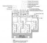
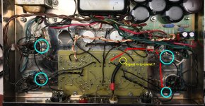
Parallel to the black wire across the this signal wire are two heater wires.
In the Dynaco manual they run along the bottom of the board until the
power take off socket then gently curve up to eyelets 4 and 5.
Then for each of the el-34 pin 4 socket to the board, are installed
100 ohm resistors. To lift?
Looking at the black wire that goes back to the tube socket in the
lower right, it actually connects to the tag board, then a 100 ohm resistor
to tube socket pin 4. Circled in light blue.
Look at the other sockets, I've circled them in light blue also.
So is this lifting the circuits to try and prevent ground hum?
Which might have started when whomever did the mods and
installed the SDS board?
FYI, when I got it the power switch had exploded and was non-existent.
Additionally, on this same left amp side, the output xrfmr was ticking/arching
or I heard that noise when I was burning in the new caps and warming up
the amp prior to setting the bias. When I investigated it, it was the secondary
positive wire for the 4 ohm tap that was intermittently arching--because of
a failed solder joint, someone did a cold 1mm lap joint splice of the wires for use with the headphone connection.
Maybe it has nothing to do with the hum. I repaired it though
using the Western Union splice. No more arching is heard.
Here is the second pic showing the resistor location.
Attachments
Sorry, my camera that loads to the PC through the micro-usb connector was taken by the burglar. The phone has a micro-usb connection but upload of pictures is prohibited. I'm suppose to send phone pictures to google, then register with google to download them. I don't need any text messages from google when I pass stores I shop with, ***** them. The phone is anonymous, a prepay one.indianajo
By chance do you still have that amp jo? if so do you pic of it?
what you describe. Not sure which deck is where, etc. Not trying
to be dense here, trying to picture it.
BTW the burglar tried to access my brokerage acccount & was stopped by the 2nd security question. He'd found the password and the answer to the first security question in my 300 lb of files.
Last edited:
Are you output transformer common taps grounded? I don't see that in the picture. Did you determine the 2 transformers have different measurements? That got lost in the shuffle.
The extra 100 ohm resistors on the power tube screens are for screen stability I expect. A reasonable mod. What I'm uncertain of is if the screen feedback wires should connect to the tube side or transformer side of that resistor. I suspect tube side, or doesn't matter.
I would be tempted to "divide and conquer" at this point, at least as a first step determine if the problem is in the output stage/transformer versus the driver by somehow feeding the output tubes 0 AC signal.
480 uf load on a 5AR4 seriously exceeds the maximum capacitance rating. Eventually it will arc across & burn. 5AR4 are $18 plus $12 freight last time I bought one. People that keep the 5AR4 but want 480 uf capacitance back up the diode action of the 5AR4 with silicon diodes. Thus the 5AR4 provides slow turn on to not hammer the signal tubes with B+ when cold. The silicon diodes do the rectification.
Silver wire versus copper wire doesn't matter at audio frequencies. What matters to 450 v currents is that the label on the wire reel says it is rated for 600 v.
What I did to replace the can cap B+ was screw a cinch solder terminal strip under the can hole. Same device as you used for the negative bias diode. Then I put one 33 uf and three 22 uf 450 v electrolytic axial lead capacitors above the deck. Negative leads were out, plus leads were in center away from the steel deck. Dropping resistors were on the terminal strip under the deck. If you did this you could take out the SDS board and put the wiring back to original locations, which works hum free.
Distance of wiring carrying 60 hz currents away from driver board pin 7 (input) is your friend when suppressing hum. Wires carrying 60 hz currents should be 90 degrees from high impedance signal wires like input jack to circuit board pin 7. If power & high impedance wires must cross, such cross should be at 90 deg and only at one point. Dynaco followed these rules.
It appears that the original ground point of the Stereo 70 was directly to the right of the multisection aluminum can electrolytic capacitor that was removed. If the can cap is bad, take it apart and avoid breaking the lugs on the can and the lugs on the phenolic. Then clean the aluminum can down to the bare shell, digging out everything. (Avoid getting the electrolyte paste on you..) Then wire (using insulating tubing) new capacitors inside the can, restore the positive (and negarive) connections on the phenolic as marked, reassemble and reinstall. This also makes the amp look original...and the ground point is preserved... New 40 or 80 uF 450 volt caps are a LOT smaller than those of 60 years ago. There should even be room to connect 100k 1 w equalizing resistors across the HV caps in series... Two 80 uF 450 v caps in series will give 40 uF with plenty of voltage headroom... Arrange the parts judiciously to fit in the can, preassemble, insulate all leads, and cover the assembly with heat shrink or other suitable insulation before placement in the can and reinstalling the phenolic.
One last comment...the 5AR4 isn't the problem...in fact it helps save components by bringing up the HV slowly...but do not exceed the maximum rated input capacitance
Last edited:
It appears that the original ground point of the Stereo 70 was directly to the right of the multisection aluminum can electrolytic capacitor that was removed.
Right next to that in my pics is where I placed the ground buss and soldered it
to chassis bolt. I should double check resistance of it though.
A 'Buss' wire is both a resistor, and an inductor.
For B+ and Bias, they have one common element, the first filter capacitors (B+ cap negative lead; Bias cap positive lead) they need to connect directly to the power transformer's secondary Center Tap. That forms a Local Ground Loop. The transient 120Hz and transient 60Hz currents (respectively) are contained locally.
Then, after containing the local loop, connect to those first B+ and bias caps (-, plus respectively) to the next capacitors in those filters; before you connect that to a central ground point.
The idea is that the transient currents are Largest there in that local loop, and have the most harmonic content of any place in the amplifier, but that by isolating those currents into a local loop, before connecting to the rest of the circuit will reduce hum and hum harmonics to the rest of the circuit.
Putting those currents onto a 'Bus' wire will inject the really small voltage drop across the Bus wire, and inject them into the most sensitive parts of the amplifier . . . the high gain input pentode for example. The negative feedback does not know if that hum and upper harmonics is the desired signal, or whether it is actually un-desired hum and upper harmonics.
I used the Stereo 70 chassis and power transformer as a test bed for many different amplifier circuits and topologies.
The first thing I got rid of was the PCB, where you have no control over things like ground loops, and no ability to modify the circuit(s).
The very worst feature of using that chassis as a test bed, is the Magnetic Steel chassis. It transmits from power transformer and B+ choke to the output transformers. That problem is most evident if you change the amplifier to a single ended amp, and use E-I air gapped laminations.
That was my first mod, pulling the Es and Is out of the A470 output transformers, and stacking them, all Es together, an air gap, and all Is together.
I isolated the RCA phono inputs from the chassis, and connected the RCA returns to the Bottom of the input tube self bias network.
Again, I formed a local loop, instead of a remote hum/transient-harmonic and noise loop. The currents from the signal source go directly to the input tube, and are not mixed with internal amplifier hum/harmonic, noise that is elsewhere in the amplifier.
Increasing the value of the first filter capacitors will increase the peak transient current, and increase the harmonics in that transient current too.
I know most of you already know this, but I hope it is a useful discussion for Newbies.
Last edited:
They are connected to eyelets 12 & 13Are you output transformer common taps grounded? I don't see that in the picture.
per Dynaco wiring diagram. But now I'm wondering if I did it correctly.
Common is the black at output pin 4 on each side. They both connect
to the ground buss, that is where the original ground lug was.
From what I could surmize, I thought they were pretty close. However, I didn't short the speakerDid you determine the 2 transformers have different measurements? That got lost in the shuffle.
terminals...common and 8 ohm taps.
Either way 100 ohm isn't muchThe extra 100 ohm resistors on the power tube screens are for screen stability I expect. A reasonable mod. What I'm uncertain of is if the screen feedback wires should connect to the tube side or transformer side of that resistor. I suspect tube side, or doesn't matter.
screen protection. I forget what might be better, I want to say
1500 Ohms off the top of my head.
What would I look for, feeding the output tubes zero AC signal?I would be tempted to "divide and conquer" at this point, at least as a first step determine if the problem is in the output stage/transformer versus the driver by somehow feeding the output tubes 0 AC signal.
Once I remove the 7199s, there isn't any more hum. Maybe it's
a combination of lead dress, ground loop, that eyelet 11 to EL34 (V3) Socket pin 4 lead dress?
How best to device and conquer?
1. Verify grounds for both speaker pin 4 black to center ground buss.
2. verifie Red-yel B+ CT does connect to ground buss.
3. verify New gray SDS ground does connect next to Red-yel B+ CT, confirmed in pics.
4. check doubling 1st bias diode cap and see if hum increases or decreases?
5. While board it up, slide the two green heater wires to right beside the
power transformer next to the SDS board edge, around the 5AR4 socket.
6. Then if those don't work solder in a new longer wire to eyelet 11 and route it around the boards edge to EL34 (V3) socket though 100 ohm to pin 4.
7. I could always shorten the ground buss wire, not sure that would have any effect though.
Okay, any thoughts to plan?
Cheers,
The central ground of most amplifiers should be after you have taken care of the local B+, & Bias loops; and after you have taken care of the input loop too.
Example, the bottom of the output tube cathode circuits are reasonably immune to hum and hum harmonic currents; but the input tube cathode circuits are very sensitive.
Think of each circuit in the amplifier in terms of how sensitive its ground return is.
Example, the bottom of the output tube cathode circuits are reasonably immune to hum and hum harmonic currents; but the input tube cathode circuits are very sensitive.
Think of each circuit in the amplifier in terms of how sensitive its ground return is.
the rule that i go by, circuits that will carry relatively bigger currents must have its own ground return separate from any signal carrying ground returns...
so yes, output tubes cathode circuits should have its own ground return wires..
so yes, output tubes cathode circuits should have its own ground return wires..
Are you output transformer common taps grounded? I don't see that in the picture. Did you determine the 2 transformers have different measurements? That got lost in the shuffle.
The extra 100 ohm resistors on the power tube screens are for screen stability I expect. A reasonable mod. What I'm uncertain of is if the screen feedback wires should connect to the tube side or transformer side of that resistor. I suspect tube side, or doesn't matter.
I would be tempted to "divide and conquer" at this point, at least as a first step determine if the problem is in the output stage/transformer versus the driver by somehow feeding the output tubes 0 AC signal.
They are connected to eyelets 12 & 13
per Dynaco wiring diagram. But now I'm wondering if I did it correctly.
Common is the black at output pin 4 on each side. They both connect
to the ground buss, that is where the original ground lug was.
From what I could surmize, I thought they were pretty close. However, I didn't short the speaker
terminals...common and 8 ohm taps.
The connections to eyelets 12 & 13 should be the feedback line from the 16 ohm outputs. Then you need a connection to the ground bus from the common taps. I'm not sure what you're referring to by "output pin 4". Have you confirmed the transformer grounding with a meter?
I got the screen resistor info here:Either way 100 ohm isn't much
screen protection. I forget what might be better, I want to say
1500 Ohms off the top of my head.
Techniques To Maximize Power Tube Life
and 100 ohm is recommended.
That sounds like the simplest way (removing 7199) so I'd say that indicates the hum is being picked up in the driver circuit. Although if the output transformer is ungrounded, that's still suspect. Next I would want to test that there isn't some issue with the fat input cable. Only thing I can think of is replace it with a plain wire or a twisted pair, grounded at one end.What would I look for, feeding the output tubes zero AC signal?
Once I remove the 7199s, there isn't any more hum. Maybe it's
a combination of lead dress, ground loop, that eyelet 11 to EL34 (V3) Socket pin 4 lead dress?
How best to device and conquer?
I'm thinking the power supply board and bias can be considered good until evidence shows otherwise, this has been a popular board for many years, we would have heard of problems if there were any, and problems there would probably affect both channels.1. Verify grounds for both speaker pin 4 black to center ground buss.
2. verifie Red-yel B+ CT does connect to ground buss.
3. verify New gray SDS ground does connect next to Red-yel B+ CT, confirmed in pics.
4. check doubling 1st bias diode cap and see if hum increases or decreases?
5. While board it up, slide the two green heater wires to right beside the
power transformer next to the SDS board edge, around the 5AR4 socket.
6. Then if those don't work solder in a new longer wire to eyelet 11 and route it around the boards edge to EL34 (V3) socket though 100 ohm to pin 4.
7. I could always shorten the ground buss wire, not sure that would have any effect though.
I'd want to confirm the transformer grounding, look at the fat input cable, then consider lead dress issues. You could also try lifting the 2 feedback lines in the problem channel as a simplification of the circuit and see if the hum stays or goes.Okay, any thoughts to plan?
Cheers,
Tony - your ground buss is insulated from the chassis? How does that work?
Is that just a lifted circuit ground? What about the other grounds?\
it is, but one side can connect to chassis metal, i also use plastic casings....
this ground buss is where all wires that needed to be zero volts are connected...
i thought i answered you earlier, it seemed i forgot to click post...
A couple more ideas: It's hard to tell from the picture, but are the heater twisted pairs pulled up and away from the board? Maybe try moving them around a little. Also have you checked the soldering on the 7199 pins? Pin 7 (input grid) on the left channel looks a little funny.
JGF - The eyelet #7 is indeed soldered well on the board.
I used shielded mic cable to see if it would help the hum,
being fully shielded and grounded at the input Jack.
Some of heater twisted pair are up some from the board.
There isn't much room for movement.
I'd have to lengthen them to move them.
Eyelets 12, 13, to the7199 board just lift them and go?
No danger to power tubes?
I thinkg I got most of what I need to do now.
Let me digest it all. I put the important stuff in
a word document so I can read it while working
on the amp.
I'll get to some later this morning
and of course putting up Christmas Stuff outside the house too, while it still
warm, not hot nor cold.
Some good stuff here....
- Home
- Amplifiers
- Tubes / Valves
- Dynaco ST-70 60 Hz Hum one channel