PRR,
TonyTecson,
6A3sUmmer,
petertub,
indianajo,
jgf,
rmb,
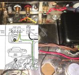
Thanks for your efforts and insights. From the attached pic
jgf got me to thinking when he said the following in post # 30.
So I was wondering from the following pic and with the Dynaco Layout
there to check on things....
That common connection on speaker jack also needs an additional ground wire to it?
You mean I should run an additional wire from IT to the Ground Buss?
Like in the Dynaco Layout?
Do y'all know how many times I've
gone through this Effing little bugger
and just put it away for another day, month,
through Covid-19, etc, etc. etc.
I haven't even soldered them commons yet,
but I'm fixin' too right after this post--Go Figure.
But I'm almost afraid too, ya know sometimes
luck doesn't change.
But it staring me right in the face.
Cheers,
Yeah, I'll let you know how it turns out.
TonyTecson,
6A3sUmmer,
petertub,
indianajo,
jgf,
rmb,
Thanks for your efforts and insights. From the attached pic
jgf got me to thinking when he said the following in post # 30.
Are you output transformer common taps grounded? I don't see that in the picture. Did you determine the 2 transformers have different measurements? That got lost in the shuffle.
I would be tempted to "divide and conquer" at this point, at least as a first step determine if the problem is in the output stage/transformer versus the driver by somehow feeding the output tubes 0 AC signal.
So I was wondering from the following pic and with the Dynaco Layout
there to check on things....
That common connection on speaker jack also needs an additional ground wire to it?
You mean I should run an additional wire from IT to the Ground Buss?
Like in the Dynaco Layout?
Do y'all know how many times I've
gone through this Effing little bugger
and just put it away for another day, month,
through Covid-19, etc, etc. etc.
I haven't even soldered them commons yet,
but I'm fixin' too right after this post--Go Figure.
But I'm almost afraid too, ya know sometimes
luck doesn't change.
But it staring me right in the face.
Cheers,
Yeah, I'll let you know how it turns out.
Attachments
Last edited:
Hi Peter, not right now.
Maybe eventually though.
No Shorting plug
Left channel 0.003VAC
right channel 0.003VAC
With shorting plugs
Left channel 0.003VAC
Right channel 0.010VAC
The plugs have loose ground.
In the system, it works fine,
no hum. none of the crap I thought
would wreck havoc on my system
when I first turned it on way back when.
Yes, cleaning it up,
tube sockets, jacks, etc.
getting correct lead dress,
etc, should take some of the
grittyness out of the music's edge.
No, I don't want to do much more with it,
for long time.
Now, I do have a Dynaco ST-70 SeriesII
that my little girl tossed a tennis ball or
something at it and took out the transistors
and bias circuit before I could shut it down.
I think the day before I warned her not to touch.
You know when kids touch a tube, they scream
bloody murder....
Any of you gent's good at those ST-70 solid state bias circuits?
Let me know and I'll start another thread fixing it.
Cheers,
Last edited:
jgf, you did do something productive yesterday and
in doing that I did something productive too!
You went a head and made my day--in a good way.
Cheers,
in doing that I did something productive too!
You went a head and made my day--in a good way.
Cheers,
My VTA upgrade
Maybe my recent adventures can be of use to someone at some future date. I opted to upgrade my ST70 with a VTA board using 6SN7 driver tubes. The kit arrived and was obviously a quality board using quality components.
I figured as long as I was under the hood I would replace all the tube sockets and the kit-built hog-wiring.
On power up, the right channel was completely dead and the left channel had a loud 60hz hum.
On the right channel I discovered that I had reversed the output wires of one of the EL34s so that the push and the pull were cancelling out each other. Easy fix. Right channel now working but it too now had a loud hum.
On this forum someone (bless his/her heart) thought that the filaments should be wired pin 2 to pin 2, pin 7 to pin 7. This was not the case with the right channel. Straightened out that problem and the right channel is working and wonderfully quiet.
Left channel still hummed but the filament wiring was correct. Hmmm.
Now what?! Being a strong advocate of the easy/cheap fix first, I criss-crossed the EL-34s and that fixed it!
Hopes this helps someone as much as I was helped.
The original Dyna Stereo 70, lets the two 6.3V filament circuits "float"
The center taps are connected to Ceramic 0.2uF caps to ground.
That means, the filament will go to an unknown voltage, according to the filament to cathode leakage of two EL34s, and the 7199 triode / pentode tube.
The 7199 triode is used as a Concertina phase splitter. The B+ that supplies the 7199 triode is divided into 3 voltages, roughly equal, Rp, plate to cathode, and Rk.
That means the cathode is at about 120VDC.
Many persons have modified the circuit with a 2 resistor divider, and a bypass cap, in order to elevate the filament center taps to about 70VDC.
I consider this to be a reasonable modification, and does two things:
Reduces the filament to cathode breakdown of the 7199, and reduces the potential hum that comes from the EL34 filament to cathode leakage that gets onto the 7199 triode's cathode.
You should check what the replacement PCB and different circuit (versus the original) does to deal with "floating" filament center taps.
Last edited:
- Home
- Amplifiers
- Tubes / Valves
- Dynaco ST-70 60 Hz Hum one channel