I'm still working on this stability issue some builders have had problems with. Amp on the bench now and running, but I need to do more tests and modelling. Its output stage parasitics from what I can tell, and its unusual with an EF2.
rocksteady can you put pictures of what you did? I'm making my own diy board from the data that Bonsai provide and yes I know is "only for personal use not for sale I agree on that 🙂 ", I'm gonna check all one more time just to be sure all is 100% correct I just found a few errors on the kx-maplifier and I need to check the PSU too
Please do NOT go ahead and make your board until the parasitic oscillation problem is solved vargasmongo
"I had and old 2W carbon resistor and 0.1u cap. Soldered them together and pressed the leads down into the top of the 0V and Zn quick disconnect connectors. Crude, not tiny by any means, but it did the trick."
Polsol/Rallyfinnen,
can you solder directly on each module PCB a 10 Ohm resistor in series with a 0.1uF cap from the amplifier side of the output coil (ie the side closest to the 0.33 Ohm emitter degeneration resistors) to the 0V where it comes in on the PCB. You need keep the leads as short as you can make them.
Can you then tell me what you see on your scope.
Thanks
Unfortunately I didn't have 10 Ohms larger than 1/4W so had to buy one.
Connected the resistor and cap with around 20 mm link.
Soldered the 10 Ohm 5W resistor to the pin to the ZN tab on the amp board and connected the 100 nF to the 0V board input using the 0V faston plug.
Amp board fed directly from the cap bank (no Ripple Eater)
The ZN is pretty close to the coil, would that make a difference?
Input shorted.
Unfortunately the oscillation has gone from around 17.5 MHz up to 18.5 MHz whilst the Volts RMS has dropped from circa 80 mV to 25 mV. 🙁
Will do some more work and take pics this weekend when I have time.
HTH
Hi Bonsai,
Just a correction.
The above results were reported with R42 'snipped' (forgot I had done that to see if it improved the 20 KHz square wave). 😱
Will resolder the joint and get back to you later with results.
Just a correction.
The above results were reported with R42 'snipped' (forgot I had done that to see if it improved the 20 KHz square wave). 😱
Will resolder the joint and get back to you later with results.
Could it be of any use to look at the current in the emitter resistors vs output voltage? I'm just thinking if the upper and lower transistors are 'in phase' at oscillation, or if there is a lot of cross conduction that is not seen in the output voltage swing? I guess cross conduction would be seen by measuring the voltage over upper and lower emitter resistors too. I'm thinking that if there is a lot of cross conduction, the currents might amplify the 'ringing' in the circuit.
If so, maybe a small cap over R19 could do some good?
Just me thinking out loud, I might be completely wrong..
If so, maybe a small cap over R19 could do some good?
Just me thinking out loud, I might be completely wrong..
That fine Tony. By snipping R42, you have simply converted the amp to standard Miller comp.
You still have the problem, which simply tells me it’s not the main feedback loop causing tne issue (sims confirm that as well).
I’ve been out this morning but will be back on the case a bit later and will report back.
Rallyfinnen, in a class A amp, you run at whatever the class A current is in cross conduction since both halves are on.
In a class AB the reason you don’t want this is often there is no current limiting across the output pairs, or, if the oscillation is very high in frequency, the current limit circuit filtering misses out the HF cross conduction.
Last edited:
OK, makes sense 🙂
I did some playing around with one channel today, but it's tricky since oscillation comes and goes. It seemed to disappear once the amp got warm. Sometimes when I have oscillation, it disappears when I touch the heat sink. When it disappeared, I could get it to oscillate again when i disconnected the load resistor.
I also have some hum/buzz even with one channel with a shorted input. Supply ripple is very low. Hum seems to get worse when the amp is grounded via the oscilloscope gnd, even If I have no safety gnd to the amp at all, and nothing connected to input, just shorted it. Jumping R9 in that situation reduces the hum significantly, but that makes DC offset go far off. I just can's see where that hum would come from. Some leakage between primary/secondary in the transformer? I even tried switching the polarity on the AC in to the transformer.
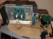
I attach a picture of my test setup. I now have two channels built like this, so it's dual mono. No ground loops should be possible. Running the ground reference for the ripple eater like this (from spk ret) seemed to give the lowest noise, and also cleanest supply voltage when the amp is oscillating.
I did some playing around with one channel today, but it's tricky since oscillation comes and goes. It seemed to disappear once the amp got warm. Sometimes when I have oscillation, it disappears when I touch the heat sink. When it disappeared, I could get it to oscillate again when i disconnected the load resistor.
I also have some hum/buzz even with one channel with a shorted input. Supply ripple is very low. Hum seems to get worse when the amp is grounded via the oscilloscope gnd, even If I have no safety gnd to the amp at all, and nothing connected to input, just shorted it. Jumping R9 in that situation reduces the hum significantly, but that makes DC offset go far off. I just can's see where that hum would come from. Some leakage between primary/secondary in the transformer? I even tried switching the polarity on the AC in to the transformer.
I attach a picture of my test setup. I now have two channels built like this, so it's dual mono. No ground loops should be possible. Running the ground reference for the ripple eater like this (from spk ret) seemed to give the lowest noise, and also cleanest supply voltage when the amp is oscillating.
Attachments
Last edited:
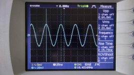
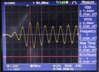
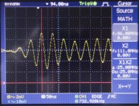
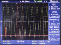
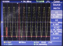
Hopefully of some value here are some waveforms with R42 now reconnected.
The probe was set at 1X and 10X and 2 sets of pictures were taken with the probe set at each position:
1) With "Cursor on" and in "Measure mode"
2) With "Cursor on" and the scope set to "Maths Mode" (RMS FFT Hanning)
According to the scope manual the specs of the probe are:
1X: 1Meg, ±128pF, DC - 6 MHz Bandwidth
10X: 10 Meg, ±23pF, DC - 60 MHz Bandwidth
Not sure whether the variance between the 2 sets is due to the probe bandwidth or the capacitance. But the change in the waveform shape seems to indicate the probe capacitance is playing a part (?)
Anyway, hopefully of some use to you.
Attachments
Some more work today just using the scope and finger 😉
Amp running, input shorted, output to 8 ohm dummy and the ZN connected 'on board'. Scope connected to the dummy 8 ohm speaker resistance.
R42 of the Miller compensation reconnected.
Oscillation at ±18 MHz and lightly pressing the following resistors with finger:
Slight Increase in waveform amplitude (± 10 - 20%): R4 (but not complimentary R5 - no discernable change)
Slight decrease in waveform (± 10 - 20%): R10, R11, R19, R38, R40, R41
Complete collapse of waveform: R1, R8, R18, R36, R37, R42
(Note R1 is not connected in circuit - i.e. running in AAB mode)
R16, R17 were inaccessible because of positioning on the PCB.
Otherwise all other resistors gave no response to lightly touching/pressing.
I've done this twice but there might be errors. If anyone wants me to crosschecked a third time please let me know.
HTH

I did some other tests on a single channel today, putting a 100uF cap over R9. This made it totally silent from hum that I had before. I'm planning to move the DC trimmer to the signal side instead of the ground, and this was just a quick first test to see what happens without R9 concerning AC.
Regarding oscillation I also noticed that it went away when the amp heated up (running full Iq mode). It was actually worse than I remembered while oscillation, with p-p amplitude at around 1V. Can's tell the frequency on my scope though, only that it's high.
In the 'transition state' (while heating up), even moving my hand close to the amp/heat sink without touching it would make the oscillation come and go.. like magic 🙂
I think the other channel is more prone to oscillation, from memory it does not quiet down totally even when warm, it still oscillates at a low amplitude.
I also started doing some distortion measurements. At low level all looked fine, but at higher output level (abt 10V RMS) I was seeing a substantial increase in high order harmonics at higher frequencies, so I will have to check if I need to damp the amplitude of the input signal to the sound card, could be the input is over-driven at higher levels. I usually don't measure at high power, but I think I have measured more than 10V without issues before.
Tony/Rallyfinnen can you clip the scope probe earth to the scope probe tip and hold the loop near your scope screen. Please make sure the scope is at Max sensitivity (2mV to 10 mV per division).
What are you seeing?
What are you seeing?
Ive done some more work on this issue today and hopefully have made some progress. Problem Ive got now is with the amp turned off Ive got 20 mV pk-pk at 20 MHz 🙁
In my case, the source of this noise is my Tektronix MOD3024 scope believe it or not. (X10 Tex probes)
In my case, the source of this noise is my Tektronix MOD3024 scope believe it or not. (X10 Tex probes)
Just checked my setup. The amp, w/o any mods, is oscillating around 16 MHz. Nothing coming off the scope with the probe ground connected to the tip.
Thanks for all the investigations that are being done.
Bob
Thanks for all the investigations that are being done.
Bob
For sake of my interest
Hi folks, I have been following this discussion for a long time, I built a KX amplifier, just for the sake of interest I proceeded as written by PolSol, my amplifier oscillates too around 16 Mhz, the output voltage for the right channel is approx. 20 mv, but for the left channel 45 mV, the inputs are short-circuited, at the output an ohmic load of 8 ohms ... interesting ...
Hi folks, I have been following this discussion for a long time, I built a KX amplifier, just for the sake of interest I proceeded as written by PolSol, my amplifier oscillates too around 16 Mhz, the output voltage for the right channel is approx. 20 mv, but for the left channel 45 mV, the inputs are short-circuited, at the output an ohmic load of 8 ohms ... interesting ...
Here an update from my work today. I will post pics tomorrow but want the amp to run a few hours to get really hot.
R20, 21, 22, 23 go from 4.7 Ohms to 10 Ohms
R42 goes to 1k
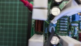
Across each 1000uF cap, i soldered a 0805 1uF 50V XR7 capacitor (note that across C35 you need to use a short piece of wire because there is a track between the capacitor pins.
I soldered a 10 Ohm 3 Watt metal oxide and 0.1uF film cap directly between the Zobel connector and speaker return on each module PCB.
Leave the existing Zobel in situ
R31 goes to 2.2 k ( this is to improve the square wave response which showed slight overshoot)
Comments
The Zobel on the kx-Amp as it is, using a wire wound resistor and located on the PSU is sub-optimal - hands in the air. It should be located on the main amplifier board, and the wire wound is also a no no. I did this because of a hang over from the sx-Amp and nx-Amps which had the Zobel on the PSU (but in both cases used parallel film caps to get higher wattage which meant the resistor inductance was << than the wire wound one.
The base stopper resistors going from 4.7 to 10 Ohms dampen any tendency for the OPS oscillate at HF. It is almost impossible to model this in LTSpice given the level of the transistor models and the PCB parasitic which can only be guessed without a network analyzer.
I went a step further and decoupled each of the 1000uF capacitors with ceramic 0805 devices.
I’ll do some distortion measurements in the next few days and post those up.
R20, 21, 22, 23 go from 4.7 Ohms to 10 Ohms
R42 goes to 1k
Across each 1000uF cap, i soldered a 0805 1uF 50V XR7 capacitor (note that across C35 you need to use a short piece of wire because there is a track between the capacitor pins.
I soldered a 10 Ohm 3 Watt metal oxide and 0.1uF film cap directly between the Zobel connector and speaker return on each module PCB.
Leave the existing Zobel in situ
R31 goes to 2.2 k ( this is to improve the square wave response which showed slight overshoot)
Comments
The Zobel on the kx-Amp as it is, using a wire wound resistor and located on the PSU is sub-optimal - hands in the air. It should be located on the main amplifier board, and the wire wound is also a no no. I did this because of a hang over from the sx-Amp and nx-Amps which had the Zobel on the PSU (but in both cases used parallel film caps to get higher wattage which meant the resistor inductance was << than the wire wound one.
The base stopper resistors going from 4.7 to 10 Ohms dampen any tendency for the OPS oscillate at HF. It is almost impossible to model this in LTSpice given the level of the transistor models and the PCB parasitic which can only be guessed without a network analyzer.
I went a step further and decoupled each of the 1000uF capacitors with ceramic 0805 devices.
I’ll do some distortion measurements in the next few days and post those up.
Last edited:
- Home
- Amplifiers
- Solid State
- Hifisonix kx-Amplifier