High SPL is one thing, amplifying the peak levels another. For 85dB speakers you better shop for a 100W/ch amplifier. At least in a 50m2 room. For the Dutch reading folks: calculator.
By reading up on these tubes and amps and by info from @ketje I was coming to the same conclusion that the power transformer is not ideal for use with EL84 tubes.
I know it was already discussed, but it seems that the "iron" I have is more suited for a larger tube like the EL34 or 5881.
Possibly a hybrid bridge rectifier might be a solution to get into the working range for an EL84 tube amp?
rebuilding the original schematic as it was doesn't seem very safe considering that they used 2 12ax7 filaments to lower the B+ with about 24VDC.
BTW my listening room is just the living room. With the couch about 3.5m from the speakers. (I also had the model of my speakers wrong. Their sensitivity 87dB in stead of 85dB, already makes some difference)
Also, to me this is just to have the experience of building/designing a functional amplifier.
If budget allows in future I might purchase more sensitive speakers. But for now it's no problem if it's just audible sound 😀
Also, to me this is just to have the experience of building/designing a functional amplifier.
If budget allows in future I might purchase more sensitive speakers. But for now it's no problem if it's just audible sound 😀
Why not buy a very cheap asian budget tube amp?
You won't beat their prices with a DIY unit. And for someone without a clear mind of what special to achieve, this will do anyway. I can suggest the trouble and time consuming only for those, who want to achieve something which isn't ready made available on the market already. Or for the connaisseur with a taste for boutique parts. He can choose every parts for his liking and sonic footprint. But for someone who just want a cheap unit, I would never suggest that long, expensive and troubling way of getting something together.
You won't beat their prices with a DIY unit. And for someone without a clear mind of what special to achieve, this will do anyway. I can suggest the trouble and time consuming only for those, who want to achieve something which isn't ready made available on the market already. Or for the connaisseur with a taste for boutique parts. He can choose every parts for his liking and sonic footprint. But for someone who just want a cheap unit, I would never suggest that long, expensive and troubling way of getting something together.
Why not buy a very cheap asian budget tube amp?
😱 That's not diy and would not recommend it anyhow.
My apologies for the somewhat harsh language @Schmitz77, but you clearly haven't read or understood the complete topic. And judging, from all your answers on this post, you're clearly not interested in what I'm after. My goal is to design/build an amplifier with the component's I have and minimal investment to have the experience of building a "First" amplifier. To experiment with it and to figure out what I'd like to build in future.
As an electronic engineer that has designed and build RF amplifiers and signal chains for space applications, I think I have the skills, patience and knowledge to learn to build these types of amplifiers.
I do not like the accusation of being "someone without a clear mind of what is special to achieve" if not given the chance of figuring that out. You will aknowlegde that there is much more to learn from redesigning an amp to fit the parts you have, than to build a predesigned amp just by putting it together.
Before writing something like the above, please take into account that there might be a reasoning behind the choices made.
I'm grateful for all people trying to help me with the project/goal I have. But Unfortunately none of your previous posts did actually help me. I hope you can understand what I'm after.
This gives us a lot more information - you clearly know your electronics and just need to carry out an experiment with tubes. What you could do is actually design the circuit yourself. If you use triode wired tubes or pure triodes you don't need any global feedback, so that makes it pretty simple. So:
1. Design your output stage. You do this by looking at the data for the tube in question on Frank's Tube site. Look at the maximum criteria and stay within them. Then look at the triode curves and choose an operating point. You can check this on the site I gave you for loadlines. Look at the pinout as well. I personally think any kind of 6L6/5881/6P3S tube wired in triode is a good starting point, as I've said. If you start with cheap new matched tubes that's one less thing to worry about. I'd choose an operating point that gives you 18W dissipation which should suit all the tubes above. So if you have 320v HT you'll probably get around 300v anode-cathode (a-k). Dissipation will be volts times amps, so 60mA per tube. Don't forget a grid resistor of 1K right on the tube socket, and a grid leak resistor of 470K down to ground from the front end of that 1K resistor, which also connects to the output of your coupling capacitor of something like 0.1uF to 0.3uF. All the data and triode curves here.
https://frank.pocnet.net/sheets/127/5/5881.pdf
2. Choose a simple front end. Probably the simplest way to go is a voltage stage followed by a cathodyne or concertina phase splitter. You'll see this explained in numerous tutorials online. Here's a good example
The Valve Wizard
3. The above front end requires 300v HT which is a useful figure for your output stage as well. You'll need isolate the front end with a resistor followed by a capacitor to drop 20v for instance from an HT of 320v. Use ohms law to size the resister and get the wattage, which should always be double the figure you get.
4. Design your power supply. 6.3v is needed for the tubes. If you use 4x 5881 that's 4x900mA = 3.6A. Add the front end, 2x ECC83 = 600mA. Total 4.2A. You'd need 6A to be conservative and avoid overheating the windings. An EL34 has 1.5A heaters so much more current needed, therefore to be simple stick with 5881/6L6/6P3S which are all 900mA. Then design your HT supply for ballpark 320v. The biggest drain will be 4 x 60mA for the 5881s = 240mA. I'm assuming your power transformer can cope with this. But if not and it gets hot, reduce the current in the output tubes to 50mA each and redesign the operating point. If that still gets hot reduce to 45mA per 5881 and redesign again.
I think that covers the basics. You might like to start drawing out a specimen schematic and then post it here and we can all trouble-shoot it. Since you're already an electronics engineer you might find it a worthwhile challenge to have a hand in your own design. And if you want to use EL84s in triode, it's exactly the same process and the same front end except your operating point will be 300v a-k, 35mA current per tube, or maybe 40mA for the tougher Russian versions mentioned. Data here:
https://frank.pocnet.net/sheets/129/e/EL84.pdf
Last edited:
With the OPT having 0-4-8-16-32Ω out it's possible to ground the 8 an use the 0 and 32 for cathode feedback.
With the extra 8Ω winding in the tube anode-cathode circuit the Raa goes up from 6k7 to 7k2.
Series resistors to lower the supply voltage and a phase splitter capable of an output of somewhat over 50Vpp it could become a nice amp.
Mona
With the extra 8Ω winding in the tube anode-cathode circuit the Raa goes up from 6k7 to 7k2.
Series resistors to lower the supply voltage and a phase splitter capable of an output of somewhat over 50Vpp it could become a nice amp.
Mona
There's so much depth of knowledge this site, sometimes generic questions get in the weeds, technically...
At some point in time, you'll just have to turn the computer off, build something and spend time listening to it from 3.5m. The acoustics will tell you where you need to go...
Then come back here for more focused advise- JMO
Most of all, have fun.
Jim
At some point in time, you'll just have to turn the computer off, build something and spend time listening to it from 3.5m. The acoustics will tell you where you need to go...
Then come back here for more focused advise- JMO
Most of all, have fun.
Jim
By reading up on these tubes and amps and by info from @ketje I was coming to the same conclusion that the power transformer is not ideal for use with EL84 tubes.
I know it was already discussed, but it seems that the "iron" I have is more suited for a larger tube like the EL34 or 5881.
Possibly a hybrid bridge rectifier might be a solution to get into the working range for an EL84 tube amp?
rebuilding the original schematic as it was doesn't seem very safe considering that they used 2 12ax7 filaments to lower the B+ with about 24VDC.
If your output transformers were used with EL84s they are likely NOT suited for EL34's. The only viable choice you would have with EL34's would be triode connection. The power rating would not be anywhere near what you need for pentode mode and power transformer too if it comes from the same radio. You can already guess by their size and weight. A transformer is not just primary impedance and besides if it was used with EL84 it is suitable for it. Datasheets do not need to be followed like a bible. They just report "optimal" (highest power within a certain distortion level, typically) for "average" tubes. Now if you get 15W instead of 18 do you think it's going make a difference? But it can also happen the contrary and get better results. Unlike commercial products you can optimize it.
On the other end running the EL34's at less than 350V is not a good idea IME. It will be likely worse than using EL84's with 7K. Just don't waste time on this. It's not the main thing at this stage really and you can always refine this aspect later.
The power supply is indeed the area where you might improve a lot.
Last edited:
That "National" power trafo has some "stones". The designers cleverly employed a bipolar PSU to provide both B+ and a negative rail for O/P tube bias and DC heater power. A pair of FWCT rectification setups are wired back to back.
How about a 1 from Column "A", 1 from Column "B", 1 from Column "C" ... ?
FWCT rectify the B+ with 2X UF5408 diodes. CLC filter the B+. A low cost Triad C-14X will do quite nicely.
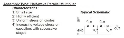
1/2 parallel voltage multiply 1 of the spare 6.3 VAC windings to obtain a negative bias rail. Use individual bias trim pots. on O/P tubes whose matching is suspect.
The Dyna ST-35 provides a straight forward signal topology. Use a 'X7 section for the voltage amplifier and a 'U7 section for the "concertina" phase splitter. The ST-35 uses self bias, but changing to "fixed" bias is NBD. As the "National" O/P transformers lack ultra-linear taps on the primary, full pentode mode will have to be employed.
Open loop linearity of full pentode mode is maximized, when screen grid (g2) B+ is regulated at some fraction of anode B+. I suggest you use 0A2 ("150" V.) gas discharge tubes (1/channel) to regulate g2 B+. I also suggest the O/P tube sockets be wired for the Russian 6Π15Π (6p15p). Sockets correctly wired for the 6Π15Π accept EL84s, without incident. 😉
How about a 1 from Column "A", 1 from Column "B", 1 from Column "C" ... ?
FWCT rectify the B+ with 2X UF5408 diodes. CLC filter the B+. A low cost Triad C-14X will do quite nicely.
1/2 parallel voltage multiply 1 of the spare 6.3 VAC windings to obtain a negative bias rail. Use individual bias trim pots. on O/P tubes whose matching is suspect.
The Dyna ST-35 provides a straight forward signal topology. Use a 'X7 section for the voltage amplifier and a 'U7 section for the "concertina" phase splitter. The ST-35 uses self bias, but changing to "fixed" bias is NBD. As the "National" O/P transformers lack ultra-linear taps on the primary, full pentode mode will have to be employed.
Open loop linearity of full pentode mode is maximized, when screen grid (g2) B+ is regulated at some fraction of anode B+. I suggest you use 0A2 ("150" V.) gas discharge tubes (1/channel) to regulate g2 B+. I also suggest the O/P tube sockets be wired for the Russian 6Π15Π (6p15p). Sockets correctly wired for the 6Π15Π accept EL84s, without incident. 😉
Attachments

Last edited:
If you want to experiment with both octal (including 6V6) and 9 pin output tubes, make the holes octal size and use adapters like these:
Tube-Town Store - Socket Converter Octal-Noval
Cookie support required | tubeface.com
Universal prototype PCB for 8Pin 7pin/9pin tube amplifier preamp headphone`v;UK | eBay
Prototype PCB for 8Pin 7pin/9pin tube amplifier preamp headphone valve HO WS | eBay
Tube-Town Store - Socket Converter Octal-Noval
Cookie support required | tubeface.com
Universal prototype PCB for 8Pin 7pin/9pin tube amplifier preamp headphone`v;UK | eBay
Prototype PCB for 8Pin 7pin/9pin tube amplifier preamp headphone valve HO WS | eBay
Last edited:
How it could be done.With the OPT having 0-4-8-16-32Ω out it's possible to ground the 8 an use the 0 and 32 for cathode feedback.
With the extra 8Ω winding in the tube anode-cathode circuit the Raa goes up from 6k7 to 7k2.
Series resistors to lower the supply voltage and a phase splitter capable of an output of somewhat over 50Vpp it could become a nice amp.
Mona
Attachments

The designs above certainly look interesting but somewhat to complex to start with. The feedback will need to be exactly right to avoid oscillations.
But after some time you have to start making decisions, so I've decided to retain with an EL84 design (initially self biased) and to start with them in triode with a 30ma current bias. If I destroy a tube, there are very affordable versions of the EL84 so easily replaced.
For the power supply I recon I can unwind some turns from the PT to get a lower voltage, say 230VAC so I'll end up at around 320VDC minus the losses of the OPT will get me somewhere around 300VDC which will be ok for these tubes. I'm aware that once done I cannot go back, but If build a new amp in the future it will use all new OPT and PT so I think no harm done.
I'll end up with something similar to an ST-35 with that. If it doesn't work I'll be probably be buying a new power transformer anyway.
Thanks again for all the inputs. I've learned quite a lot in the last few days. Now it's time to get building and experimenting.
I'll post the recalculated schematic to have a second opinion from you guys.
Last edited:
I absolutely would NOT unwind your mains transformer. It's not necessary. It's a nice transformer and good as it is.
Just get a choke. You should have a choke in your power supply anyway. Then just use a small polypropylene first capacitor. Get some 2.2uF at 630v and add them until the voltage is what you want - 4.4uf, 6.6uF etc. Or get a packet of 1uF.
10x Capacitor 1uf 5% 630V DC Polypropylene Axial Valve Metal Film Audio UK | eBay
As for a choke, Hammond do plenty. e.g. 158S, 158T, 159S, 159T. Anything rated for 225 to 300mA. Larger the better.
If you don't have a centre tap you can use a hybrid or Graetz bridge with a tube rectifier handling the positive side and 2 x UF4007 the negative side.
The Valve Wizard
Make a nice traditional tube PSU and do it properly. Your power transformer is perfect for this. If you use a tube rectifier it will drop volts anyway. A 5R4G drops plenty of volts.
JAN 5R4GA PHILIPS ECG 5R4 5R4G NEW OLD STOCK VALVE TUBE 1PC JLY15 | eBay
Last edited:
Thanks Eli,
According to this http://www.thehistoryofrecording.com/Manuals/DynaCo/Dynakit_ST35.pdf
there is indeed 370VDC (to chassis) on the tube. Va-k is 356.5VDC
So you think these tubes will survive that?
According to this http://www.thehistoryofrecording.com/Manuals/DynaCo/Dynakit_ST35.pdf
there is indeed 370VDC (to chassis) on the tube. Va-k is 356.5VDC
So you think these tubes will survive that?
I absolutely would NOT unwind your mains transformer.
I concur. Just use as many LC (or RC) sections as you need to drop the end B+. I’d use at least 1 L.
dave
Andy,
I'll certainly try what you recommend. Choke and capacitors.
As for the bridge rectifier. If I would use a hybrid, I will need at least 2 EZ81 tubes, no? One for each channel. As these tubes have a maximum current rating of 150mA I was told.
I'll certainly try what you recommend. Choke and capacitors.
As for the bridge rectifier. If I would use a hybrid, I will need at least 2 EZ81 tubes, no? One for each channel. As these tubes have a maximum current rating of 150mA I was told.
You can use 2 x EZ81 in parallel. Don't split channels, keep it simple. Just make sure you get new EZ81s so they measure pretty much the same.
If you need any more capacity for the 6.3v circuits, just get a separate 6v transformer as big as you need. If it's specified for double the current you need it will end up giving you around 6.3v, maybe even a little more.
If you need any more capacity for the 6.3v circuits, just get a separate 6v transformer as big as you need. If it's specified for double the current you need it will end up giving you around 6.3v, maybe even a little more.
Last edited:
- Home
- Amplifiers
- Tubes / Valves
- EL84 tube amp build, how to start?