I don't think BD139/140 are so expensive to need fakes, but use a DBT to bring it up and you should be able to tell very quickly if the bias or offset is unstable.
I have built 6 FH11 (same design with 2-pair of outputs) and the bias is rock-solid from start-up to hours of listening.
I did build a dim bulb tester and I will use that.
I was wondering if for a first startup (checking assembly, bias, etc) if it made any sense to use my LM317/LM337 power supply. Set to something like +/-10 to +/-15V. (A minimal voltage to check for gross faults with the speed of a semiconductor/LM317 for current limiting.)
Does that make any sense? Does anyone do that? Or should I just pick my lowest voltage transformer and go with the dim bulb tester?
Attachments

You could use the variable supply, but I generally use the DBT with a 40w/60w bulb and if everything goes well try with a 150w bulb as final test. A 150w bulb on small amplifier may only reduce DC voltage 2-3 volts, unless there’s a problem.
Then I test for DC on speakers and play some music at low volumes. If it all checks out, I take the DBT out of circuit and re-check and set final bias and enjoy.
Then I test for DC on speakers and play some music at low volumes. If it all checks out, I take the DBT out of circuit and re-check and set final bias and enjoy.
A5 schematic need
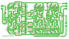
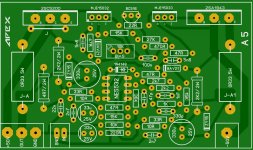
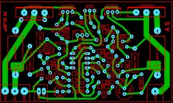
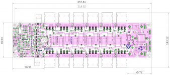
hi every one...a need apex A5 schematic but i have PDF of pcb...but for check and redesign i need schematic...
its look like mini PCB and powerfull...
hi every one...a need apex A5 schematic but i have PDF of pcb...but for check and redesign i need schematic...
its look like mini PCB and powerfull...
I did build a dim bulb tester and I will use that.
I was wondering if for a first startup (checking assembly, bias, etc) if it made any sense to use my LM317/LM337 power supply. Set to something like +/-10 to +/-15V. (A minimal voltage to check for gross faults with the speed of a semiconductor/LM317 for current limiting.)
Does that make any sense? Does anyone do that? Or should I just pick my lowest voltage transformer and go with the dim bulb tester?
Most of my diy amplifiers tested using this method.
I use two bench power supplies, one for the positive rail and the other for the negative.
Smoke free!
You could use the variable supply, but I generally use the DBT with a 40w/60w bulb and if everything goes well try with a 150w bulb as final test. A 150w bulb on small amplifier may only reduce DC voltage 2-3 volts, unless there’s a problem.
Then I test for DC on speakers and play some music at low volumes. If it all checks out, I take the DBT out of circuit and re-check and set final bias and enjoy.
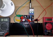
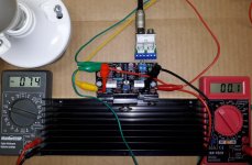
Well I took a hybrid approach with both the Dim Bulb Tester and the LM317/LM337.
Of the two AliExpress FH9 one biased up with a reasonable bias current at +/-18V while the second flashed the bulb and measured 230 mV (about 0.5V). [At only +/-18V.] So I quickly brought the bias down. These have 0.25 Ohm emitter resistors so I set 75 mV across the two (0.5 Ohms) or 150 mA.
I am glad I did not power up with +/-45V initially because I think the one that flashed the dim bulb with the cranked bias would have been in trouble.
With both at 150 mA they sound nice. In particular I thought the bass was very good. I am not sure how exactly to describe it but perhaps I could say that the bass was very "flowing" and "musical". Is that the experience of others with the FH9?
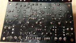
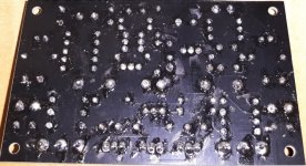
If others buy these from AliExpress beware that the bias might not be set right (one of mine was good, the other very high) and that the soldering is messy and should be carefully checked. Perhaps turn down the bias pot before first power up just in case. I used a 60W bulb.
Can I ask what is the optimum supply voltage for 4 Ohms for this design? I do not want to use excessively high supply voltage resulting in excessive output transistor heating with 4 Ohms.
Attachments
APEXAUDIO MM38?
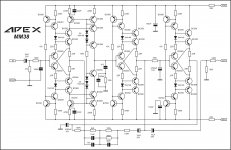
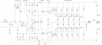
Hello, APEXAUDIO. Tell me MM38 working scheme. He began to make a test assembly, spread the board, assembled. And the scheme does not want to work. Power supply + -24V. Is there already a ready-made board for assembly? Here's my option that I'm testing. What can be a rake?
Hello, APEXAUDIO. Tell me MM38 working scheme. He began to make a test assembly, spread the board, assembled. And the scheme does not want to work. Power supply + -24V. Is there already a ready-made board for assembly? Here's my option that I'm testing. What can be a rake?
Attachments

Hello, APEXAUDIO. Tell me MM38 working scheme. He began to make a test assembly, spread the board, assembled. And the scheme does not want to work. Power supply + -24V. Is there already a ready-made board for assembly? Here's my option that I'm testing. What can be a rake?
Post voltage measurements on transistors pins.
All fet buffer
Mister Miele, please tell me with which letter index it is better to use the Y, GR or BL transistors.
Thanks.
Everything works fine without this circuit.
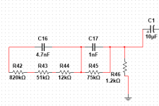
Add reverse RIAA on input.
Attachments
Mm38
Replace with a new scheme. 10,000 Hz earned. But at 1000 Hz and below, everything is curved.
Replace with a new scheme. 10,000 Hz earned. But at 1000 Hz and below, everything is curved.
Dear Mr Mile, I would like to build a strong amplifier to use for partying, which has 150W minimun of power output and cheap power transistos like the 2N3055 or similar. Could you suggest one of your schemes for this pourpose? Thank you.
Dear Mr Mile, I would like to build a strong amplifier to use for partying, which has 150W minimun of power output and cheap power transistos like the 2N3055 or similar. Could you suggest one of your schemes for this pourpose? Thank you.
BX22
Thank you Mr Mile for your prompt repplay. If I want to use only 2 pair of 2SC5200 & 2SA1943 instead of six, how much should I reduce the supply voltage?
There are something to change (resistors) for what above?
There are something to change (resistors) for what above?
- Home
- Amplifiers
- Solid State
- 100W Ultimate Fidelity Amplifier