So I have to measure the pin itself, nothing coming from it? Would it be a good idea to insulate the probes up to the very tip?
You have to leave a bit of metal showing for the probe to electrically connect.
Just be careful and (using my previous diagram as an example) measure on parts that you can see connect to the pins if that feels safer.
So put your negative meter lead on ground and touch the positive lead onto for example the appropriate end of the feedback resistor and just note the voltage.
Just be careful and (using my previous diagram as an example) measure on parts that you can see connect to the pins if that feels safer.
So put your negative meter lead on ground and touch the positive lead onto for example the appropriate end of the feedback resistor and just note the voltage.
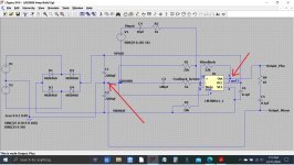
I've got: pin: 1 +27v, pin 3: 0 pin 4: -27v, pin 5: +27v, pin 7: 0, pin 8: -0.45, pin 9: 0, pin 10: 0
Well that is looking much much better 🙂
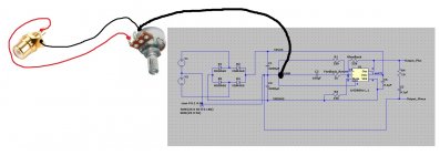
So the next step is to wire the chip to the speaker socket.
1/ Connect a wire from the left hand section of the short ground stub wire to the negative speaker terminal. This is important. The connection has to be further toward the left (so nearer to the large reservoir caps) than all other ground connections made so far. The actual distance doesn't matter, just so long as it is more toward the big caps.
2/ Connect another wire from Pin 3 of the chip (which is the output of the chip) to the positive speaker terminal.
(we have already correctly wired the Zobel network so ignore how they look on my diagram)
3/ Switch the amplifier on and confirm the DC voltage as measured across the speaker terminals is close to zero volts.
Assuming that it is you can now connect a speaker to the socket. Read carefully... we connect the speaker across the terminals while the amp is still ON.
The speaker should remain essentially silent although you may hear a tiny hiss if you go up close to it and/or a tiny level of hum.
If that is OK then disconnect the speaker and turn the amp OFF.
Attachments
Wonderful 🙂
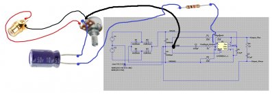
So now we wire one of the input sockets up. I'm assuming you are using RCA sockets (phono sockets).
1/ Connect a wire from the ground part of the socket to what will be the ground tag of one gang of the volume control.
2/ Now connect the ground tag of the volume control to the clean ground which is the right hand end of the stub of wire as shown.
3/ Connect the other end pin of the volume control to the centre input pin of the socket as shown.
Follow the diagram:
Attachments
Now we connect the middle pin of the volume control to the chip.
1/ Connect a 1k resistor onto pin 10 and close to the chip. This is the non inverting or '+ input'.
2. Connect a 10uF cap to the centre pin of the volume control. The cap can go either way around at this stage.
3/ Connect the cap to the resistor as shown.
Note... try and keep the resistor as close to pin 10 as possible. Use the resistor leg itself to solder to the chip in order to keep it close, no need for actual extra wire. I've only shown wire in the diagram to show the connectivity.
Solder the capacitor lead direct to the volume control and only use wire to link the two parts.
And that is basically it 🙂
Turn the volume to minimum.
You should now recheck the DC voltage at the speaker socket is still zero (no speaker attached). Keep using the bulb at this stage.
If that all is OK then switch OFF.
(With the amp OFF you should read almost a short circuit (zero ohms) between the middle pin of the volume control and any ground point such as the outer part of the RCA socket. This just confirms you have the control wired correctly)
Connect the RCA socket to a suitable source such as a CD player and play a disc.
Switch the amp ON.
Now connect the speaker.
Now turn up the volume.
Attachments
IT WORKS! It only bloody works doesn't it?!!!!!!! Thank you SO much, I was really losing the will to carry on 🙂 I am one happy soul 🙂 🙂 🙂
🙂 Well I'm really really pleased to hear that... and nothing beats first hearing sound from your first amplifier.
Wonderful.
Wonderful.
What now? I obviously have to make the other channel. Can I use common wires for things like the ground? Do I ideally need to change the caps that I substituted? I will need to order some more stuff, can you give me a shopping list? 🙂
Essentially you just duplicate what you have built connecting all the same points in parallel to what we have now.
You use the same end of the same ground stub for the same connections we have already in place.
The power supply pins for the second chip wire back to the same points as this one do. Same for the Zobel network return and the speaker ground return.
The input is where it can get slightly different because we will have two grounds to deal with but initially you can just duplicate what we have here.
Duplicating is probably best. You know this one now works. A second one literally in parallel and overlaid on top of this should be just the same.
Don't rush it but follow the exact same steps and tests as we used for this one.
The only different parts I can think of are that you should get some smaller 10uF 63 volt caps and also perhaps some very small ones such as 470pF (Pico Farad) that can be added as an input filter.
All that comes later though. You need to build the other channel as a duplicate of this one.
Okay great and thanks so much again for all of your help 🙂 I'll set to it. Thank god for a lockdown! 😉
One question: In my original build there were ground wires all over the place. Does none of this have to connect to a chassis ground?

Just take it slowly and check along the way.
That little ground wire is the most important connection point and so everything in the second channel must connect to that same 'electrically clean' end of that little wire in just the same way that everything does now.
One question: In my original build there were ground wires all over the place. Does none of this have to connect to a chassis ground?
By chassis ground do you mean a metal case?
It doesn't necessarily have to do so although, with a metal case it does make sense to connect the case to the zero volt point of the circuit and so gain benefit from shielding.
All that can come later though.
The input sockets should be electrically isolated from from a metal case as should the speaker negative terminal. The RCA sockets in that case should be the ones with plastic insulating washers.
The case is not used for connectivity at all, it is purely referenced to the zero volt line on the amplifier.
Wonderful.
You explain things very well to a novice, even the grounds. And a lot of people are confused about proper grounding in audio circuits.
I've found that proper grounding is at least half the battle when it comes to audio circuitry.
- Home
- Amplifiers
- Chip Amps
- Complete novice alert! *don't read if easily annoyed by stupid questions*