I had the same doubt,
if i had to guess, the led behavior logic was mis-interpreted.
from what i see, it seems that the led was intended as positive switched... while the uC board bypass a series current resistor towards ground.
I think for a "standby" <> "operation" effect.
I think you can work around that by using the +5 line from the encoder and then (bypassing the trimpot) feed back via the led pin.
... there's always the possibility that i have brain farted, and mis-understood completly the initial intention of the designer 🙂 so... take my speculations with the proper grain of salt.
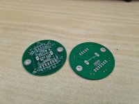
on my side i have designed an adapter to better suits my needs.
View attachment 894146
if it works as expected i can share the gerbers.
what is the suppose of this board? can you explain it to me?
thx
what is the suppose of this board? can you explain it to me?
thx
IF that works as expected...
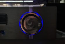
same board will be mounted to both left and right encoder, uses the 6v voltage line for the uC board to drive 6 (or 3...) led. the led will be the backlight of my "big" knob. like that (photo don't make justice...)

(that with just one led to see the effect)
they should ramp to full brightness ( ~2s ) when uC trigger it, and then ramp down to idle brightness when in standby.
One board will be the master, the other a slave. daisy chained.
... but that is all to be tested
Last edited:
@Chris, can you check the encoder board. Sorry for my doubts but I don't see + power supply for LED. As my understanding, P1_7 is connected to P4_1 on uC board that is also ground connection.
Just let me know.
I had the same doubt,
if i had to guess, the led behavior logic was mis-interpreted.
from what i see, it seems that the led was intended as positive switched... while the uC board bypass a series current resistor towards ground.
I think for a "standby" <> "operation" effect.
I think you can work around that by using the +5 line from the encoder and then (bypassing the trimpot) feed back via the led pin.
... there's always the possibility that i have brain farted, and mis-understood completly the initial intention of the designer 🙂 so... take my speculations with the proper grain of salt.
on my side i have designed an adapter to better suits my needs.
View attachment 894146
if it works as expected i can share the gerbers.
Sorry, just now seeing this. Yes, that is probably an error as this was done very quickly and I hadn't asked about the LED, but assumed. And we all know what happens with that.
IF that works as expected...
same board will be mounted to both left and right encoder, uses the 6v voltage line for the uC board to drive 6 (or 3...) led. the led will be the backlight of my "big" knob. like that (photo don't make justice...)
View attachment 894217
(that with just one led to see the effect)
they should ramp to full brightness ( ~2s ) when uC trigger it, and then ramp down to idle brightness when in standby.
One board will be the master, the other a slave. daisy chained.
... but that is all to be tested
FYI, just in case you didn't notice.
The current controller board already implement a similar functionnality except it doesn't ramp gradually between the 2 brightness settings.
Led(s) are supposed to connect on P4 (between pin 1 and 6) and you may change the default resistors values (R18 and R19) in order to achieve the two brightness levels of your taste.😉
yes...
sure, already noted, as reported just few posts above...
My implementation is to carry two separate circuit, one for left and one for right encoder, with more current capability to drive 12 led in total.
Also i need a way to attach the 6+6 led to the front panel, and a pcb was a natural way to do that. Furthermore, two hex spacer will secure more nicely the pcb to the front panel.
Brightness ramp up / down is a collateral feature that cost me nothing to implement (always if it works as expected). Beside that, via firmware i think is achievable the very same effect in the current state of things by just pwm'ing the gate of the mosfet across the limiting resistor... not ideal, but could work.
The FW is ready with the VFD, all functions implemented and another 3 little non problematic bug fixed. Actually I never let the VFD so long on my preamp but I kind of like it. Very nice too. If the opening on my front panel was so not so large I will probably leave it there.
I will switch back to OLED to check that everything is good then put it on HCFR.
Overall lots of improvements so a good upgrade for all. I will describe what was fixed.
I will switch back to OLED to check that everything is good then put it on HCFR.
Overall lots of improvements so a good upgrade for all. I will describe what was fixed.
Hi Gionag
Thank for your reply. Your board seems to be very interesting. Can you share its circuit and gerber file? I will use mechanical encoder but I would like to get some ideas from your design.
Best regards.
Thank for your reply. Your board seems to be very interesting. Can you share its circuit and gerber file? I will use mechanical encoder but I would like to get some ideas from your design.
Best regards.
I had the same doubt,
if i had to guess, the led behavior logic was mis-interpreted.
from what i see, it seems that the led was intended as positive switched... while the uC board bypass a series current resistor towards ground.
I think for a "standby" <> "operation" effect.
I think you can work around that by using the +5 line from the encoder and then (bypassing the trimpot) feed back via the led pin.
... there's always the possibility that i have brain farted, and mis-understood completly the initial intention of the designer 🙂 so... take my speculations with the proper grain of salt.
on my side i have designed an adapter to better suits my needs.
View attachment 894146
if it works as expected i can share the gerbers.
OK Chris. It is clear.
Best regards.
Best regards.
Sorry, just now seeing this. Yes, that is probably an error as this was done very quickly and I hadn't asked about the LED, but assumed. And we all know what happens with that.
Hi Gionag
Thank for your reply. Your board seems to be very interesting. Can you share its circuit and gerber file? I will use mechanical encoder but I would like to get some ideas from your design.
Best regards.
I'll surely do when i am sure it works correctly... 😀
The FW is ready with the VFD, all functions implemented and another 3 little non problematic bug fixed. Actually I never let the VFD so long on my preamp but I kind of like it. Very nice too. If the opening on my front panel was so not so large I will probably leave it there.
I will switch back to OLED to check that everything is good then put it on HCFR.
Overall lots of improvements so a good upgrade for all. I will describe what was fixed.
needless to say...
thank you
Hi,
For the Component GB, Mouser order has been done this morning ... almost 6000€, amazing.
There are some backorders, so I don't know exactly when the order will be delivered.
Alex
For the Component GB, Mouser order has been done this morning ... almost 6000€, amazing.
There are some backorders, so I don't know exactly when the order will be delivered.
Alex
Well those backorders have some delivery dates.. which is the last one? How many weeks?
there is not indication in the order.
I check one part which is not available , it say 41 WEEKS ... really 😱
Anyway the muse chips are also out off stock, they are given for 18 weeks
Last edited:
So one like me that didn’t order the muse chips for when can hope to receive the order?
Btw you can order the muse chips from here MUSES72320V-TE2 2 Channel Electronic Volume Control | Profusion
They have more than 1000 in stock.
Btw you can order the muse chips from here MUSES72320V-TE2 2 Channel Electronic Volume Control | Profusion
They have more than 1000 in stock.
There is where I bought mine.So one like me that didn’t order the muse chips for when can hope to receive the order?
Btw you can order the muse chips from here MUSES72320V-TE2 2 Channel Electronic Volume Control | Profusion
They have more than 1000 in stock.
If I recall correctly they are also far cheaper than mouser...
So one like me that didn’t order the muse chips for when can hope to receive the order?
Btw you can order the muse chips from here MUSES72320V-TE2 2 Channel Electronic Volume Control | Profusion
They have more than 1000 in stock.
Eric...... You might wanna look at that. Far better prices than Mouser´s, even after their discount, and the GroupBuy is all about saving money, I suppose??
Apparently, we have 13 references ins backorders including the muse chip.
I was able find an equivalent reference directly by mouser for some of the missing items.
I putted the details in this sheet:
CG UGS Muse v2.0 (DiyAudio 2020) - Components - Google Sheets
For the leftover including the muse chip, I could order them from Digikey (everything is available)
Price-wise we should be in the same range, about 17€/u.
What do you think?
- Home
- Amplifiers
- Pass Labs
- UGS-muse preamp GB
