
@JensToft91
You should probably avoid expensive componets at this point. What matters more is that you find component values, and a circuit, that allow you to get the best from your speaker, something you can live with. If this is wrong then it hardly matters how much you paid for the parts.
You should probably avoid expensive componets at this point. What matters more is that you find component values, and a circuit, that allow you to get the best from your speaker, something you can live with. If this is wrong then it hardly matters how much you paid for the parts.
There is no question that the accuracy of Xsim is fine. In addition however, a crossover is a part of a bigger picture. There is no simple answer to your question.than I can just simulate a crossover, and it works in practice.
The null is simply a crosscheck. Trying to get it sharp is a wild goose chase.null
@ akarma 76
Is that an auto-transformer?
If it is, then I'd begin by ignoring it. By leaving it out, you are simulating an 'ideal' component at the 'maximum' setting. If you knew the inductance you could include it, to figure in the finite reactance at the low end due to limited inductance of the component.
There are techniques you could use to adapt with Xsim, ie. for simming other than 'maximum' setting. For example, by using the speaker sensitivity slider, and adjusting the first capacitor value accordingly. Another would be to measure the impedance before the autoformer at different attenuation levels..
Is that an auto-transformer?
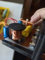
Coil from Tannoy MX2 crossover
Attachments
OK, lets perhaps assume this is an unknown quantity.. this is a way to work around it.
Install C4, L2 and the resistor on to your driver, but leave out C3. Apply your test signals to the resistor in place of the driver. Measure the impedance, and your response(s).
Use these measurements in Xsim. For the circuit sim, use only C3, don't include C4, L2 or the resistor. You can add other components if you choose, to get the response you need.
If, however, you want to change C4, you need to repeat your measurements.
Edit: I'm of the mind that the resistor would be 180 ohms.. it certainly wouldn't be 0.18
Nice to see this thread is still active after so many years. Tribute to the really great utility this piece of software provides. One thing I haven't found in the help file on if the 80 odd pages of posts on the forum is how to create default 16 ohm driver. I'm hot rodding an old pair of JBL 4828 stage monitors into home stereo speakers and I need to model a 2426J driver without simply putting a pair of 8 ohm drivers in series.
Thanks for any suggestions
Thanks for any suggestions
You could trace the manufacturer data.
https://www.parts-express.com/pedocs/specs/294-412-jbl-2426j-specifications.pdf
https://www.parts-express.com/pedocs/specs/294-412-jbl-2426j-specifications.pdf
<<<SNIP>>> I'm hot rodding an old pair of JBL 4828 stage monitors into home stereo speakers and I need to model a 2426J driver without simply putting a pair of 8 ohm drivers in series.
Thanks for any suggestions
There's some very good topical info in this thread over at LHF
- There's even an already worked out HP for you to transpose to a different impedance.
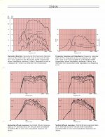
Two things to wrap your brain around is that the 2426J is more like a 10ohm driver.
The other is the quite mediocre ( raw ) response of the driver on that horn.
( The horn imposes a few significant notches into the otherwise fine response of that driver )
🙂
Attachments
Last edited:
Thanks for the link Frank. Oddly enough I found that thread last evening and modeled in XSim the 2426 high pass that the OP had posted. I've actually been using a set of these 4828 wedges in my shop for years along with a pair of 2226s as low boxes but I've always run the set up triamped with a DSP crossover. I was able to get a very flat response and very precise arrival times with the DSP but was thinking of going with passive crossovers to use the speakers in my living room. After looking at the response curves on that 2344 spec sheet I think I'll just go back to biamping the speakers and finding a small stand alone sub. I hadn't seen that page of 2344 response curves before despite having four wedges with those horns for a decade. Helps to have a copy of Smaart and a lot of DSP crossovers handy for rolling your own.
Xsim problem
Hey there!
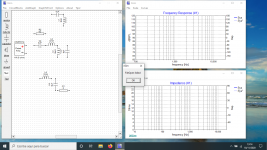
I´m experiencing a problem with Xsim in my laptop. Operation seems just fine, but trying to open a saved project gives a error message, louspeakers and component figures dissapear, like in the attached picture. Some error in my machine configuration, maybe?
Someone solved a similar problem before?
Hey there!
I´m experiencing a problem with Xsim in my laptop. Operation seems just fine, but trying to open a saved project gives a error message, louspeakers and component figures dissapear, like in the attached picture. Some error in my machine configuration, maybe?
Someone solved a similar problem before?
Attachments
Hey there!
I´m experiencing a problem with Xsim in my laptop. Operation seems just fine, but trying to open a saved project gives a error message, louspeakers and component figures dissapear, like in the attached picture. Some error in my machine configuration, maybe?
Someone solved a similar problem before?
I don't know if it'll help but when creating XSim design make sure to use .frd and .zma file extensions for measurements. It's easy to overlook in for example Clio Pocket system which by default uses .txt file extension for frequency and impedance characteristics export. Using proper file extensions once helped me to overcome similar kind of problem.
Also decimal separator character other than period (.) in response files or number settings in Windows control panel has caused problems. Works okay for sure when everything in system and files looks like American.
Thanks for the responses, but no, the problem arises when I try to re open any just worked, and saved *.dxo project.
^Have you started whole new project so that decimal separator settings and file formats are okay for sure? Corrupted existing project may require editing of project file with some text editor.
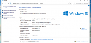
Xsim worked always flawlessly on my old WIN8 machine, and still does. I checked it again today. 
Can you not right click Xsim and run as Win8 or earlier settings to see if it's a current Win10 issue?
- Home
- Design & Build
- Software Tools
- XSim free crossover designer