Hi guys,
Good news I got allmost all the payment
Bad news a made a mistake in the price list, all the advertised price are without VAT 🙁
We have to add 20.6% on mouser price list .... sorry for that 🙁
Good news I got allmost all the payment
Bad news a made a mistake in the price list, all the advertised price are without VAT 🙁
We have to add 20.6% on mouser price list .... sorry for that 🙁
Exactly what I was thinking .... sorry for that.
if any of you wants to cancel, I will understand.
Just let me know.
Alex
if any of you wants to cancel, I will understand.
Just let me know.
Alex
Had the opportunity to take a picture of the correct orientation.
For future reference...

Last edited:
did you update the amount in the list?Exactly what I was thinking .... sorry for that.
if any of you wants to cancel, I will understand.
Just let me know.
Alex
should only affect the mouser stuff?
thx
yes the amount has been update in the gsheet, it's only affecting the mouser parts.
BTW the transformers have been ordered
BTW the transformers have been ordered
Had the opportunity to take a picture of the correct orientation.
For future reference...
View attachment 893063
The relay should actually be on the opposite side of the PCB compared to your picture when using the sub board with the UGS Muse.
The relay should actually be on the opposite side of the PCB compared to your picture when using the sub board with the UGS Muse.
You are obviously right, my photo is wrong, i have mis-interpreted completly.
i will try to contact a moderator to change it for a correct photo... otherwise i risk to do more damage than help 🙂
Nice to know !
... I have started my handevour for two main purposes :
1. to better refine my code writing skill
2. to be able in future to manage the feature as my own please
Beside that, you have made clear more than one time that new feature development will be suspended/interrupted (pun intended) and you will only bugfix the current feature set.
I have not a clear idea on what direction I will take, but i want to experiment and be in control 🙂
The request about the "tunable" gain setting for refining the gain i have requested... please, implement it only if that make sense also to you and only if you think can be a nice addition to the current firmware.
If you are doing that only for me, and just for me, then, spare your time and go ahead with the release of the firmware without that. I was thinking that can be a good thing to have for everybody, but maybe i was wrong.
Just that.
Yes I said that I will focus only on fixing bugs but what else should I do?
Add more software features? The software I implemented is already providing more flexibility / options than the UGS AI that I was supposed to take as the reference so I am not sure what is missing here?
And at one point I believe that I need to stop adding custom features otherwise this might be endless.
Talking about stopping adding custom features by the way, I implemented this morning the tunable gain in both symetric / asymetric, so consider this done + I think the dual encoder should work now, I just need to wire a switch to try.
And as most were requesting, you have now the dual encoder control and the 6 switches together, so it is up to you to do what you want : 1 encoder + 6 switches, two encoders, two encoders + up to 6 switches.
As you like.
@alex: soooo many thanks for your effort and your time and work. we are all very thankful and we appreciate your skills and your will to help.
great news with the new features and your new implemented software add ons.
so many thanks.
great news with the new features and your new implemented software add ons.
so many thanks.
Thanks Fencki 🙂
Then I just checked the switch on the second encoder and I confirm that finally it works very well with all the possible pressing options, found my bug.
What I need to do now is to wire a second encoder on the board and make sure that the rotation is working well (but I have high confidence on this one) and then put back my OLEDs and check that all the things I added are displaying well on the OLEDs too.
I will add as well another configuration menu for the second encoder where you can decide the rotation direction (no need to swap the wires you can connect the way you want) and the stepping (division by 1, 4 or 8). Those are new features on the existing volume encoder and that will be as well on the source encoder.
Once this is done I'll release the new firmware to all of you.
Probably need another week.
I just connected a second encoder and I confirm that it is working well.
Stones you don't need to worry, the dual encoder is implemented and working 😉
Stones you don't need to worry, the dual encoder is implemented and working 😉
Please confirm...Coming back to the Sub Board.
The BOM have not been corrected?.. 10k resistor have been replaced by a 4,7k and a 50k Trimmer right?
The BOM have not been corrected?.. 10k resistor have been replaced by a 4,7k and a 50k Trimmer right?
Ready to test with my setup if you are willing to share the beta.I just connected a second encoder and I confirm that it is working well.
Stones you don't need to worry, the dual encoder is implemented and working 😉
Already have my email
I just connected a second encoder and I confirm that it is working well.
Stones you don't need to worry, the dual encoder is implemented and working 😉
It’s an early Xmas for me, that’s great thanks Alex
@Chris, can you check the encoder board. Sorry for my doubts but I don't see + power supply for LED. As my understanding, P1_7 is connected to P4_1 on uC board that is also ground connection.
Just let me know.
Just let me know.
Alex,
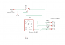
Here is the gerber file for the Bourns encoder board. I also included the Eagle .brd and .sch files. I sent you a pm regarding my order as well.
Thanks,
Chris
Attachments
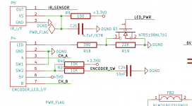
@Chris, can you check the encoder board. Sorry for my doubts but I don't see + power supply for LED. As my understanding, P1_7 is connected to P4_1 on uC board that is also ground connection.
Just let me know.
I had the same doubt,
if i had to guess, the led behavior logic was mis-interpreted.
from what i see, it seems that the led was intended as positive switched... while the uC board bypass a series current resistor towards ground.
I think for a "standby" <> "operation" effect.
I think you can work around that by using the +5 line from the encoder and then (bypassing the trimpot) feed back via the led pin.
... there's always the possibility that i have brain farted, and mis-understood completly the initial intention of the designer 🙂 so... take my speculations with the proper grain of salt.
on my side i have designed an adapter to better suits my needs.

if it works as expected i can share the gerbers.
Last edited:
A friend of meine jumps out and so I have a set left, if you have interest please contact me.
Will put also an offer in „Swap Meet“, thanks.
1 x uC board
2 x pos / neg shunt board
2 x rear board
2 x UGS pre amp board
1 x main power board
1 x sub board
1 x logic board
1x amp trigger board
1 x source trigger board
2 x output buffer board
2 x UGS board
2 x encoder board
Please take a look, thanks.
- Home
- Amplifiers
- Pass Labs
- UGS-muse preamp GB