So, not the magnetic field or the diode noise.
Perhaps, before doing the ZM, you might isolate the protection board, and the supply to it (just undo the connections) - and at the same time, check the wiring of the speaker return (neg terminal) - might be a loop there.
You might also consider moving the soft start circuit pcb too - either to the middle of the back panel or next to/in front of the power transformer and maybe run the mains wires down the centre/bottom of the case in an earthed metal jacket/mesh sleeve over the mains wires, but first, find the 'hum'.
Now that my yuichi horns and jbl 2450 arrived, I hooked up the f6 instead of the ACA, and really liked what the f6 did to the sound compared to the ACA. However , the slight hum on two way monitors is now quite loud on the horns (20db more efficient). Loud as in, I can easily hear it from 3 meters away. So troubleshooting began with several leads from this great forum and specifically this thread:
1. Inputs shorted; hum only with head in front of horn.
2. Input shorted, one channel powered up; even quieter, definitely would be happy with this, as hum is only noticable with head inside horn😉
My first conclusion is that the PSU is related to this slight imcrease in hum between one and two channels connected, correct?
But then:
3. RCA jacks connected; similar to #1
4. Interconnects plugged in on F6 side only; louder hum
5. Interconnect between f6 and 6-24 crossover, loudest hum.
6. Interconnect between f5 and wayne line stage; equal to #5
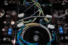
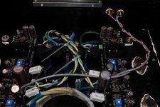
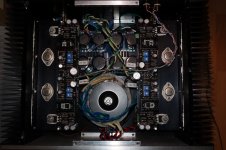
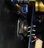
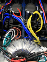
See attached photos how I wired everything up. (transformer bolt is not touching the chassis) Ia have already moved signal ground to psu directly and tried without the two signal grounds connected. I am comfused as to what should be my next move?
Your help is much appreciated!
(fyi, waiting for the 15 inch woofers to arrive)


1. Inputs shorted; hum only with head in front of horn.
2. Input shorted, one channel powered up; even quieter, definitely would be happy with this, as hum is only noticable with head inside horn😉
My first conclusion is that the PSU is related to this slight imcrease in hum between one and two channels connected, correct?
But then:
3. RCA jacks connected; similar to #1
4. Interconnects plugged in on F6 side only; louder hum
5. Interconnect between f6 and 6-24 crossover, loudest hum.
6. Interconnect between f5 and wayne line stage; equal to #5
See attached photos how I wired everything up. (transformer bolt is not touching the chassis) Ia have already moved signal ground to psu directly and tried without the two signal grounds connected. I am comfused as to what should be my next move?
Your help is much appreciated!
(fyi, waiting for the 15 inch woofers to arrive)
Last edited:
when dealing with crazy horns, best recipe is to build either monoblocks or dual mono
that way you can expect least hum
that way you can expect least hum
Thanks ZM, next one (hopefully VFET pt 3!) will be mono.
But that only solves that bit of hum related to the psu which increases with load, right?
There must be something, I guess related to signal gnd, that I am missing.. .
By the way, should there be continuity (dmm) between signal gnd and the base plate next to the thermistor?
But that only solves that bit of hum related to the psu which increases with load, right?
There must be something, I guess related to signal gnd, that I am missing.. .
By the way, should there be continuity (dmm) between signal gnd and the base plate next to the thermistor?
See attached photos how I wired everything up. (transformer bolt is not touching the chassis) Ia have already moved signal ground to psu directly and tried without the two signal grounds connected. I am comfused as to what should be my next move?
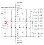
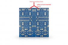
You could try to decrease hum by having GND connection of left and right part of power supply PCB on the output end only.
Attachments
Robin,
I agree with Zen Mod regarding duo mono or monoblocks for sensitive horns. I have 103db horns and I have no noise issues with my amplifiers. I have monoblocks and a duo mono, but I also managed to get my one amplifier with shared bipolar power supply quiet too.
Initially the shared power supply amplifier was noisy. I found this article by diyAudio member Bonsai that was of great help to me:
http://hifisonix.com/wordpress/wp-content/uploads/2019/02/Ground-Loops.pdf
Things that I do in all my amplifiers:
1. Twist all wire together with their returns. I see that you have done that except for the power transformer secondaries.
2. Rotate the power transformer to find the position of least noise. Your transformer may be there already.
3. Keep the power transformer as far away as possible from audio signal wires and circuits, especially low level (input) signals. You have done that. I also run the AC wires down the middle of the amplifier, away from the left and right amplifier boards.
At this point my diyAudio Sony VFET amplifier with the shared power supply was noisy. After much frustration, I managed to make it quiet. I don't know whether it was one thing, all of the things, or a combination of some of the things I did, but this is what I did:
4. On the diyAudio power supply board, I joined the V+ and V- ground together with wires in the form of a T or Y and connected all grounds to the board at the joined end.
5. I added a local RC filter at each amplifer board for both V+ and V-. They can be seen in the pictures. I used 0.1R and 1000uF. The capacitors were not identical between V+ and V- because I did not have four identical capacitors, so I used what I had on hand.
6. I reduced the total loop area of the wires by moving the left signal input RCA jack to right next to the right input jack. I joined the two grounds at the jacks and then took the two channels' wires to the input on the right channel and then continued the left channel wires across to the left channel board.
7. I also bundled the left and right channel V+, V-, Gnd wires together down the center of the case until they were in line with the power input of the boards and then branched them off to the respective boards. Again, this was to reduce total loop area.
I also have all of my audio equipment plugged into the same wall outlet, and I keep all of the power cords bundled together as long as possible before separating to individual components.
Again, I have to say that the Bonsai/hifisonix article was most helpful in providing me with tips to quiet my amplifier. I strongly urge you to read the article. It has a lot of theory to start with but towards the end, there is a section with very useful practical information.
Regarding your question about signal ground and chassis ground, with the CL60 thermistor connecting the two, the measured resistance between signal ground and chassis ground shoud be the cold resistance of the thermistor, which is about 10 Ohms.
Attachments
I did not build this amp and indeed there were many issues I had to address to get it bias correctly.
Though not ideal (or good practice I know) but I cant see how these shaped pins would cause hum.
Though not ideal (or good practice I know) but I cant see how these shaped pins would cause hum.
They don't cause harm if bent correctly, and they certainly won't cause hum.
He is just joking around.
He is just joking around.
Thanks ZM, next one (hopefully VFET pt 3!) will be mono.
But that only solves that bit of hum related to the psu which increases with load, right?
There must be something, I guess related to signal gnd, that I am missing.. .
By the way, should there be continuity (dmm) between signal gnd and the base plate next to the thermistor?
It looks like maybe you have a transformer internal shield tied to chassis ground. My F6 was quieter with that shield not connected (floating).
Robin,
I agree with Zen Mod regarding duo mono or monoblocks for sensitive horns. I have 103db horns and I have no noise issues with my amplifiers. I have monoblocks and a duo mono, but I also managed to get my one amplifier with shared bipolar power supply quiet too.
Initially the shared power supply amplifier was noisy. I found this article by diyAudio member Bonsai that was of great help to me:
http://hifisonix.com/wordpress/wp-content/uploads/2019/02/Ground-Loops.pdf
Things that I do in all my amplifiers:
1. Twist all wire together with their returns. I see that you have done that except for the power transformer secondaries.
2. Rotate the power transformer to find the position of least noise. Your transformer may be there already.
3. Keep the power transformer as far away as possible from audio signal wires and circuits, especially low level (input) signals. You have done that. I also run the AC wires down the middle of the amplifier, away from the left and right amplifier boards.
At this point my diyAudio Sony VFET amplifier with the shared power supply was noisy. After much frustration, I managed to make it quiet. I don't know whether it was one thing, all of the things, or a combination of some of the things I did, but this is what I did:
4. On the diyAudio power supply board, I joined the V+ and V- ground together with wires in the form of a T or Y and connected all grounds to the board at the joined end.
5. I added a local RC filter at each amplifer board for both V+ and V-. They can be seen in the pictures. I used 0.1R and 1000uF. The capacitors were not identical between V+ and V- because I did not have four identical capacitors, so I used what I had on hand.
6. I reduced the total loop area of the wires by moving the left signal input RCA jack to right next to the right input jack. I joined the two grounds at the jacks and then took the two channels' wires to the input on the right channel and then continued the left channel wires across to the left channel board.
7. I also bundled the left and right channel V+, V-, Gnd wires together down the center of the case until they were in line with the power input of the boards and then branched them off to the respective boards. Again, this was to reduce total loop area.
I also have all of my audio equipment plugged into the same wall outlet, and I keep all of the power cords bundled together as long as possible before separating to individual components.
Again, I have to say that the Bonsai/hifisonix article was most helpful in providing me with tips to quiet my amplifier. I strongly urge you to read the article. It has a lot of theory to start with but towards the end, there is a section with very useful practical information.
Regarding your question about signal ground and chassis ground, with the CL60 thermistor connecting the two, the measured resistance between signal ground and chassis ground shoud be the cold resistance of the thermistor, which is about 10 Ohms.
Thanks Ben Mah for your detailed description! This leaves me with plenty of things to read and improve upon. I am still concidering the slb psu as an upgrade from current, and of course for future builds.
@1543 will cut the first traces, thanks for the tip,
@avdesignguru will remove the screen and see if it helps.
This arrived at my doorstep today🙂
Faital 15pr400

laverda,
Can you please carefully check if the Jensen transformers are properly soldered to the board?
Does your power transformer hum or rattle in any way under load?
Can you please carefully check if the Jensen transformers are properly soldered to the board?
Does your power transformer hum or rattle in any way under load?
So, I spent most of this evening decanting the PSU off board and rewiring (twisting to night away).

Sadly the hum has not diminished..
As suggested by zman01 I'm going to take a closer look at the amp boards!! Again!!!

But...Iv'e just tried my bench PSU 'NO HUM' just sweet sweet music...Pointing too the PSU??
Sadly the hum has not diminished..
As suggested by zman01 I'm going to take a closer look at the amp boards!! Again!!!
But...Iv'e just tried my bench PSU 'NO HUM' just sweet sweet music...Pointing too the PSU??
Last edited:
I've also tried my known good PSU from my F6 and AJ but in this F6 they also have the hum issue. WTF
Pretty sure the PSRR of the Aleph J is significantly better than F6.
If you have sensitive speakers it could be as simple as you need to beef up your power supply filtering.
Or go dual mono etc.
If you have sensitive speakers it could be as simple as you need to beef up your power supply filtering.
Or go dual mono etc.
laverda,
Can you please carefully check if the Jensen transformers are properly soldered to the board?
Does your power transformer hum or rattle in any way under load?
No noticeable noise from the transformer.
I've also tried my known good PSU from my F6 and AJ but in this F6 they also have the hum issue. WTF
Though I have no experience with the DIYAudioStore 'Universal' power supply boards, it seems there may be something wrong with them if your bench PS gives no hum. I would do a thorough inspection of the boards, connections, even possible bad caps?
I'll have to admit, the AliExpress boards featuring all Made in China Rover "Audio Grade" Capacitors

 worked very well. I had initials issues with hum and knew the the Jensen input transformer would attract noise.
 After inspection, power each universal PS board up - get your DMM and measure the output noise. Could be defective caps?

And I don't know why people are obsessed with oversized washers to squeeze down the TO-247 transistors. I founds these nice rectangle ones from my early days of hanging out at the local scrap metal recycling facilities (a time when I hunted for large heatsinks).

Good Luck!
I've also tried my known good PSU from my F6 and AJ but in this F6 they also have the hum issue. WTF
Hang on.
You're saying you have another F6 that doesn't have this problem?
Is that correct?
With a know good power supply.
Check isolation of RCA jacks from chassis, replace all rca cables, check all the dumb stuff, that is usually what it is 90% of the time.
Last edited:
But...Iv'e just tried my bench PSU 'NO HUM' just sweet sweet music...Pointing too the PSU??
Attachments
That's the link to ensure both halves of the board share a common 0V connection for the dual polarity psu. Only one end of the board needs to be joined together though, so yeah if both ends are linked then snipping that connection is probably worthwhile.
It only needs to be joined at the 0V star end of the PSU.
It only needs to be joined at the 0V star end of the PSU.
Last edited:
- Home
- Amplifiers
- Pass Labs
- F6 Illustrated Build Guide