Even though there is another recent thread devoted to the new GRS ribbons, I thought I would start this new thread that compares the frequency response and distortion for the following:
My primary interest for all of these drivers is in dipole or open baffle systems with little to no baffle (e.g. nude) so I measured all of them "in the nude". To do this, I used the following:
Prior to starting the measurements for any driver, the SPL was measured at the mic tip using the SPL meter, and the level was adjusted to be 96dB using bandlimited (>200Hz) pink noise as a stimulus. This output is equivalent to 90dB at 1m distance. Levels remained identical during all subsequent tests on the driver.
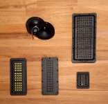
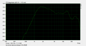
Below, please find a pic of the drivers used. Starting from the two dome dipole and moving clockwise are the PT5010, PT2522, LM8K, and the Asian Neo8 copy at bottom left. Not shown: Neo3PDRW. All drivers were used right out of the box, without break-in. No series capacitor was used for these tests. I did not perform any impedance measurements.
.
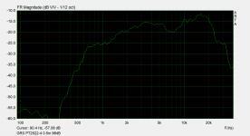
- GRS PT2522-4 (Neo3 copy)
- B&G Neo3PDRW
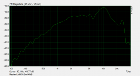
- Radian LM8K
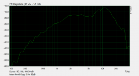
- Unbranded Asian copy of Neo8
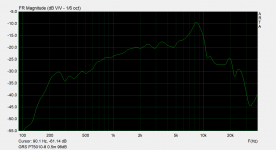
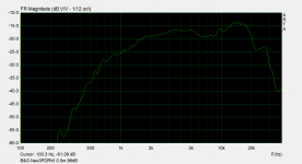
- GRS PT5010-8 (Neo10 copy)
- back-to-back dome tweeters as a dipole
My primary interest for all of these drivers is in dipole or open baffle systems with little to no baffle (e.g. nude) so I measured all of them "in the nude". To do this, I used the following:
- All drivers were suspended by wires about 4-5 feet off of the ground
- Measurements were taken in a room with 7 foot ceiling, about 15 feet wide and 40 feet long
- ARTA and STEPS were used to perform the measurements, running on a Windows laptop
- The mic was an Earthworks M30BX, placed at 20in (~0.5m) from the driver
- Audio interface was a Focusrite Clarett 2Pre USB
- Amplifier was a Parasound Zamp v3
- SPL meter was the Galaxy Audio CM-130
Prior to starting the measurements for any driver, the SPL was measured at the mic tip using the SPL meter, and the level was adjusted to be 96dB using bandlimited (>200Hz) pink noise as a stimulus. This output is equivalent to 90dB at 1m distance. Levels remained identical during all subsequent tests on the driver.
Below, please find a pic of the drivers used. Starting from the two dome dipole and moving clockwise are the PT5010, PT2522, LM8K, and the Asian Neo8 copy at bottom left. Not shown: Neo3PDRW. All drivers were used right out of the box, without break-in. No series capacitor was used for these tests. I did not perform any impedance measurements.
.
Attachments
Last edited:
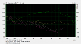
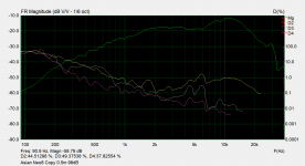
First up are the frequency responses.
Attachments

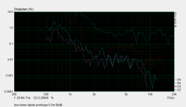
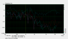
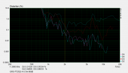
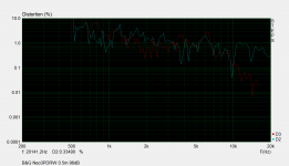
Next is the distortion for each driver measured in ARTA (I like to call this a "quick distortion measurement").
Attachments
-
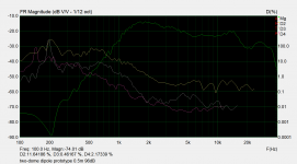 two-dome dipole prototype quick distortion.png87.9 KB · Views: 1,408
 -
 GRS PT5010-8 quick distortion.png63.1 KB · Views: 1,932
 -
 Asian Neo8 Copy quick distortion.png62.3 KB · Views: 957
 -
 Radian LM8K quick distortion.png62.3 KB · Views: 954
 -
 B&G Neo3PDRW quick distortion.png89.2 KB · Views: 1,124
 -
 GRS PT2522-4 quick distortion.png87.7 KB · Views: 1,205
Finally, distortion measured using STEPS.
NOTES:
I did not perform a STEPS measurement for the Asian Neo8 copy so I don't have the data for it.
I accidentally overwrote the Neo3PDRW STEPS datafile with the STEPS measurement for the two-dome dipole. I will remeasure the Neo3PDRW and repost it later.
NOTES:
I did not perform a STEPS measurement for the Asian Neo8 copy so I don't have the data for it.
I accidentally overwrote the Neo3PDRW STEPS datafile with the STEPS measurement for the two-dome dipole. I will remeasure the Neo3PDRW and repost it later.
Attachments

Last edited:
While performing the STEPS re-measurement of the Neo3PDRW it died and there was a "smell". I noticed that it, and the GRSPT2522, had become warm during the tests - the GRS was slightly less warm than the B&G from what I recall. I didn't think much about it at the time. The signals used in STEPS are essentially high power constant sine waves. In hindsight, the STEPS test is probably delivering more power than these two drivers can dissipate. Oh well, lesson learned. I got the two Neo3s off of Ebay as new last year and while they did look new you never know.
I re-tested the other Neo3PDRW and the resulting STEPS data is shown below.
I re-tested the other Neo3PDRW and the resulting STEPS data is shown below.
Attachments
Thank you very much for your measurements.
I have been very interested especially in the distorsion measurements of the LM8K. But now I'm honestly a little bit disappointed. I hoped to be able to use it as a single naked midrange driver down to about 600Hz.
But your measurement show me, that you should not use it this way below 800Hz or even a little bit more.
However it is still worth trying them with a good midwoofer.
A direct comparison with the Neo8s will be very interesting.
Yes, thanks much for posting. A lot of work but important to see comparisons. What were the domes and if anonymous brand, a word about their design?
Post #80, linked below, shows my FR and THD plots for an ESL cell, a bit bigger than the ribbons. Not easy to compare the two test set-ups, but in my biased opinion, the ribbons sure look lousy next the the ESL plots.
New planar drivers at Parts Express
B.
Post #80, linked below, shows my FR and THD plots for an ESL cell, a bit bigger than the ribbons. Not easy to compare the two test set-ups, but in my biased opinion, the ribbons sure look lousy next the the ESL plots.
New planar drivers at Parts Express
B.
Thank you very much for your measurements.
I have been very interested especially in the distorsion measurements of the LM8K. But now I'm honestly a little bit disappointed. I hoped to be able to use it as a single naked midrange driver down to about 600Hz.
But your measurement show me, that you should not use it this way below 800Hz or even a little bit more.
However it is still worth trying them with a good midwoofer.
A direct comparison with the Neo8s will be very interesting.
Yes, based on distortion I think that 800Hz would be a good choice for crossover point. It depends a bit on the order of the crossover - lower orders like LR2 will be rolling off the power above the crossover point, so you MIGHT be OK going a little lower in frequency. It would be a good idea to measure the driver on the final speaker and see how low you can get away with.
Yes, thanks much for posting. A lot of work but important to see comparisons. What were the domes and if anonymous brand, a word about their design?
Post #80, linked below, shows my FR and THD plots for an ESL cell, a bit bigger than the ribbons. Not easy to compare the two test set-ups, but in my biased opinion, the ribbons sure look lousy next the the ESL plots.
New planar drivers at Parts Express
B.
I saw that - why aren't there any modern versions of that? Looks pretty good!
The domes I used are Dayton ND25FW-4. It's a 25mm dome in a waveguide with a neo motor. I have crossed these over as low as 1.6kHz. The drivers are not expensive, but sticking two of them back-to-back is tricky. They can just about nest that way if the mounting holes are used and the drivers are offset a bit. For this particular prototype I cut away some of the waveguide so that the motor of one driver could rest up against the motor of the other. This keeps the side-to-side and front-to-back offsets of the acoustic centers to a minimum. I have to do off axis measurements to see how the pattern holds up but even with a slightly larger spacing, an un-altered pair actually has a very good dipole pattern.
I tracked down a link for the "Asian Neo8 clone" that I included in the measurements. You can find it here:
2 PCS/LOT Diy monitor audio flat monitor HiFi speaker high power ribbon tweeter planar transducer AMT Neo8|Combination Speakers| - AliExpress
2 PCS/LOT Diy monitor audio flat monitor HiFi speaker high power ribbon tweeter planar transducer AMT Neo8|Combination Speakers| - AliExpress
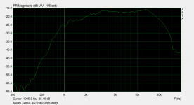
Here is another small planar driver to consider for dipole use: the Aurum Cantus AST2560. This driver is provided as a magnet assembly that includes a removable/replaceable "diaphragm" that are screwed onto a mounting plate. It is a simple matter of a couple of screws to remove the mounting plate, and what you get is a very small and compact unit that is mostly diaphragm. A thin felt pad covers the rear of the assembly but it can be peeled off. There are four dead-end threaded holes (for the faceplate mounting screws) that can be used to secure the guts to something (e.g. baffle or whatever).
I forgot I had this stored up for testing as a potential dipole driver, so I didn't include it along with the other drivers earlier in this thread. After having the Neo3PDRW burn up on me I have decided to no longer use STEPS for tweeter distortion testing.
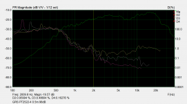
Plots of the on axis frequency response, and the "quick distortion" test, are attached. I used the same test conditions: 96dB at 0.5m with the driver suspended by wires.
This driver looks usable as a tweeter above 2kHz or so.
I forgot I had this stored up for testing as a potential dipole driver, so I didn't include it along with the other drivers earlier in this thread. After having the Neo3PDRW burn up on me I have decided to no longer use STEPS for tweeter distortion testing.
Plots of the on axis frequency response, and the "quick distortion" test, are attached. I used the same test conditions: 96dB at 0.5m with the driver suspended by wires.
This driver looks usable as a tweeter above 2kHz or so.
Attachments
Last edited:
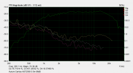
After testing the AST2560 above and while I had it on my test fixture, I decided to take a couple of quick off-axis responses and plot them together to see how it looks as a dipole. I used angles of (very approximate here) 0, 22, 44, and 66 degrees. It's not bad, really. The directivity of the pattern seems pretty constant until you get up above 10kHz. See attached plot.
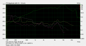
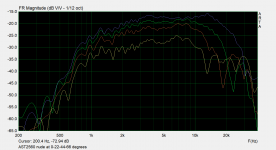
Well if I can do that I might as well do the same thing for the GRS PT2522 (Neo3PDR clone). After a few quick measurements, I had the 0-22-44-66 response family for that as well. But this time I found something, mmm, not great. The response around 7k has some issues. This is, not surprising and is very similar to the Neo3 dipole response. On axis there is a dip or partial null. As you move off axis this first goes away and then becomes a peak. The curves all bunch together and even cross. Eek. Just like what was observed for the Neo3 as a dipole. It's a real clone, down to the flaws and all. The plot of the response family for the GRS PT2522 is attached below.
When I was looking up info on the Neo3PDR recently I came across an old thread on audiocircle from a guy who used a 3D printer to make strips that he glued on to the outside of the Neo3 between the slots. This seemed to tame and smooth some of the response on axis but he did not provide off axis data. It might be that a similar treatment could improve the pattern with the GRS version.
BG NEO 3 FR optimization
NOTE: The GRS PT2522's 7k Hz on-axis dip is sharper in this measurement compared to the one that I provided previously. I think I was not quite on-axis the first time around. What you see here is truly on-axis for the 0 degree trace.
.
Attachments
Last edited:
Nice FR plot but rather poor HD. Isn't that an expensive unit?
Hard to know the right level for testing tweeters. They aren't called on to play loud on music. Maybe far better if quieter test. Is there a 3D graphic for freq, level, and THD?
B.
Hard to know the right level for testing tweeters. They aren't called on to play loud on music. Maybe far better if quieter test. Is there a 3D graphic for freq, level, and THD?
B.
Nice FR plot but rather poor HD. Isn't that an expensive unit?
Hard to know the right level for testing tweeters. They aren't called on to play loud on music. Maybe far better if quieter test. Is there a 3D graphic for freq, level, and THD?
B.
For home audio that is getting up there in level. But that should be better at revealing flaws I suppose. Because the sweep only lasts a second or two I am not worried about damage all that much.
There is a distortion plot on the MFG product page for the AST2560 (see link in my post) that shows lower levels of distortion. Maybe a lower SPL level was used for it, and if so that is a good sign.
Yeah these are getting more expensive now. They were UD$40-50 each cheaper when I bought them, and right after that there was a price increase. Not sure why. Still, it costs much less than anything by Mundorf!
Edit: here is the MFG distortion plot - they do not provide the testing conditions, e.g. SPL, etc.:
An externally hosted image should be here but it was not working when we last tested it.
.jpg)
Last edited:
Many thanks for your measurements, and your continued work on dipoles.
Cheers,
Ian
+1
and subscribed.
This driver is provided as a magnet assembly that includes a removable/replaceable "diaphragm" that are screwed onto a mounting plate. It is a simple matter of a couple of screws to remove the mounting plate, and what you get is a very small and compact unit that is mostly diaphragm. A thin felt pad covers the rear of the assembly but it can be peeled off. There are four dead-end threaded holes (for the faceplate mounting screws) that can be used to secure the guts to something (e.g. baffle or whatever).
. . .
Plots of the on axis frequency response, and the "quick distortion" test, are attached. I used the same test conditions: 96dB at 0.5m with the driver suspended by wires.
Was this test run with the felt damping removed or in place?
Was this test run with the felt damping removed or in place?
Both the faceplate and the rear felt layer were removed prior to making the measurement.
I've considered using the AST2560 as a dipole, matching it with the Purifi PTT6.5 (also dipole). I would only do so if it was equally low distortion as the PTT6.5 (or close). Based on your measurements, I'm not sure it reaches that level of performance. Would you agree?
Unfortunately, I've only found dome tweeters that do, specifically the Bliesma tweeters and the SS 9900 and I can't afford using 2 of those back to back for dipole.
Unfortunately, I've only found dome tweeters that do, specifically the Bliesma tweeters and the SS 9900 and I can't afford using 2 of those back to back for dipole.
It would be nice if anybody had a cogent rationale for what should be broadcast from the back.*
B.
* besides Bose
B.
* besides Bose
- Home
- Loudspeakers
- Planars & Exotics
- measurements of nude ribbons and a dome-dipole